Do you want a search engine that works like old Google? Distributed and run by the people? Free and open source? No ads or tracking? Mastodon for search engines????
I’m going to introduce to YaCy, which is exactly that. Then break your heart and tell you why it doesn’t work.
YaCy is a distributed search engine and crawler which uses similar tech to torrents (distributed hash tables). It allows for anyone to start crawling websites and running a search frontend. The peer to peer nature of it means that while your node might not have crawled a specific site or information, another node might have - allowing for searches to be distributed across the network and hopefully returning a result for your query.
Some time ago I wondered, on modern internet connections and todays cheap storage, how hard could it be to run your own search engine. YaCy popped up in my searches and I thought I would give it a go. Estimates for Google’s index size vary from 30 billion to 400 billion. That might seem like big numbers but for computers these a tiny. Also to make things easier we can limit ourselves to purely text documents and if we avoid indexing useless or low value websites we can bring that number right down. My finger in the air estimate is that a search engine with 3 billion indexed high quality pages is going to be just as useful for most people.
With that in mind I bought a beefy box from OVH, configured YaCy and set it crawling the web. In less than a month its indexed 24 million pages.
while the entire YaCy network has around 2.4 billion indexed documents. My node can easily index 1000 documents a minute if given the chance. One of the neat things about YaCy is the concept that a website can run their own node to provide search results for their site search and any other remote queries on the network. For example Wikipedia could run their own official Wikipedia YaCy instance.
It all falls apart when you try to use it however.
Search results are often lacking useful content and more often than not unofficial/low quality pages will rank higher than official or trusted sites. Often I just random ftp servers, tar balls and zips. Now there’s probably some settings I can tweak to make site ranking a bit better - but it’s not a good start.
Slight tangent here. While playing around with YaCy I also found SearXNG. It’s an opensource metasearch engine. You configure multiple search backends and when you search it performs that search across all of them. So you can get Google, Bing, YaCy, DDG all in one. If using YaCy I suggest setting this up. I’d love to have the results from other search engines then get fed back into YaCy to index.
This brings me towards why YaCy isn’t really usable today (or probably ever). Google Search from yesteryear just wouldn’t work today. A lot of content is behind walled gardens - such as Facebook and X. But ignoring these areas modern webpages are JavaScript heavy - often empty pages that are loaded through API requests.
I hear you screaming “what about SEO?!?”. Apart from SEO being silly, it’s now GEO, Google Engine Optimisation. Displaying or rendering content specifically for Google. If you attempt to scrape websites using the YaCy user agent you are often left with disappointment. If you think you can just switch to a Googlebot user agent your left with being blocked by WAFs and CloudFlare for not coming from the right IP / AS number or other types of fingerprinting. Places like StackOverflow try very hard to not have their content scrapped as it would destroy their business model.
Today we have a new problem, AI scraping. YaCy practically appears no different to an AI scrapper when using a Googlebot user agent. The AI scraping shitstorm has effectively stopped another search engine crawler from existing.
Regardless of the crawling issues, the way we use search engines, and the quality they provide has also shifted. YaCy’s basic search algorithm just isn’t suitable. The key component to this is having the search engine understand not just the word but the context of the word. For example “monitor” could mean a computer monitor, or to watch something. The search engine should use the other words in the query to determine which pages relate to the type of monitor. This is especially important given the rise of keyword stuffing and AI generated slop.
Side note about AI slop. One of the things I have found surprising is that YaCy has very rarely given me results for AI slop. I’m not sure if this is because AI slop is less indexed, or the SEO optimisation that AI slop performs isn’t effective with YaCy, but it is an interesting observation.
We also expect additional features, for example I often search for “time in $x” and “weather” to get quick previews. Maybe for these I should move to tools outside a search engine.
YaCy itself is dated. It’s a fairly old project and development has slowed down. Slow development itself isn’t a problem but it’s design and architecture leaves a lot of be desired. I get the vibe that there’s probably some security issues hidden in the old code base waiting to be discovered. The other part is that I don’t think there’s been enough attention to privacy and moderation. The controls they have today kind of work, but it’s not something I’d suggest using if you want your queries to be kept private. It’s very easy for crappy spam to end up indexes as well.
My other concern is that if everyone was to rush out and install this software, we’d have a ton of people scraping popular (or even non popular) websites like Wikipedia unnecessarily. How to balance freedom and coordination here is a little tricky.
That doesn’t mean YaCy is all bad. It can run in several modes - the one I’ve been talking about is the “community based web search”. While I haven’t tested it out yet, there is also “Intranet indexing” which you may find useful for indexing your local file server.
YaCy remains a project I want to succeed and work well. The dream and concept is great. Reality unfortunately places it in the not very useful category.
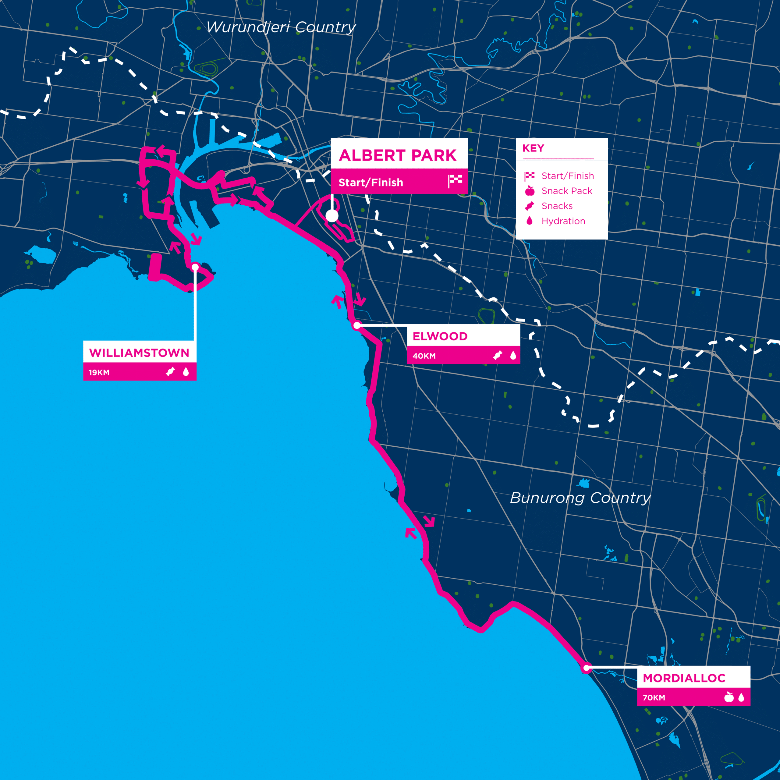
If you follow my partners YouTube channel, Drop Table Adventures, you’ll be well aware that they have been entering the “Around the Bay” cycling event for several years now. Specifically “The Classic” route. This is a 220km circuit….. around the (Melbourne) bay.
This year on a bit of a whim, and within 5 days until the event I decided to buy a ticket for the 100km route. Then I checked the weather. I should have checked the weather first.
The 100km route leaves Albert Park, over the West Gate bridge to Williamstown, back across West Gate, follows the bay towards Mordialloc before returning to Albert Park.
A 100km ride is big for me. The last time I rode 100km was in high school. Made even more challenging in that I hadn’t trained for this. But I felt strong when I purchased the ticket.
Challenges:
Scoliosis - riding long distances has historically been extremely hard on my back
No training - I did a 40km social and slow ride about a month prior, and a 20km about 2 weeks prior
Still somewhat recovering from my last bike crash
I don’t really have much experience in group riding
3 days prior I managed to give myself food poisoning (stomach related fun seems to be a reoccurring problem when I enter events it seems)
The 100km route requires crossing the West Gate twice - so a bit of elevation change compared to just riding the bay trail
On my side:
Have been keeping fairly fit, swimming, short runs
Competing in the commuter cup 2-3 days a week
Prep
To give myself the best shot of making the distance I stripped my bike of the lock, front and rear racks. Given the weather I left the mud guards on (more of a courtesy to other riders but seems I was alone here). With no racks, I had a small saddle bag which carried a toolkit, bacon strips, tyre levers, a tube, my phone and a pump.
For hydration and fuel I carried… an AARNet water bottle. I decided to rely on the rest stops for fuelling needs. In hindsight I probably should have packed at least a single gel.
Go
Since I had traveled with Droppy and Alex to the event, I was very early for the 100km start. This meant I found myself at the start of the pack. It’s not a race so it doesn’t matter so much, but it certainly grouped me with some riders that were probably a little bit fitter than me.
Leaving the start line I was filled with “oh god what have I gotten myself into” as I kept up with some very expensive bicycles being ridden by people that at the very least looked the part. I on the other hand was wearing a loose fitting running top and running tights with my budget gravel bike. There was some slight drizzle but it was otherwise not bad conditions to ride in. Moving speed was around 30km/hr.
Hitting the west gate though and that speed dropped right back to 16-20km/hr, but I was still keeping up with the main pack. The pack was cruising at closer to 28km/hr after the bridge which was a bit closer to what I could handle.
At 18km we hit the first rest stop - I decided to keep riding through. The pack thinned at this point but I clearly wasn’t the only one continuing through. Back over the bridge and on the other side I felt that my legs were a bit more like Jell-O™ now (40km in). Unfortunately the pack split up a bit due to traffic lights and eventually I was practically alone. At this point I was considering skipping the next stop and continue straight onto Mordialloc (70km in).
However at 45km logic prevailed and I realised I needed fuel and a top up of my water. So when the 50km Elwood rest stop came up I entered. At this point I found myself in an interesting situation - I was too fast to be in the casual riding groups and too slow to keep up with the serious groups. At Elwood rest stop I entered while they were practically still setting up. I think I saw two other cyclists. I was still able to grab a banana and some water. Was hoping that there would be some hydralite. Onwards!
This next section between Elwood and Mordialloc was horrible, the worst even. I’m not sure if it was just because I was low on energy or the way the elevation changes occur, but speed dropped significantly on the slight uphills. The downhills didn’t feel like they lasted for long. A couple of packs over took me here, I tried to keep up for a bit but just couldn’t. Regardless still averaging around ~25km/hr. I was riding alone for pretty much all of this section.
Arriving at Mordialloc (70km) I was sore. I knew I had to spend some time at this stop. I grabbed some crisps, trail mix, and a gel. While eating I spent some time sitting and standing to give the muscles that keep my back in check a break. Legs were feeling ok, but not strong. During this time I overheard that rain would be coming at 11am. At this point I decided that maybe, just maybe I could make it back dry.
While the Elwood/Mordialloc stretch was the hardest, the Mordialloc to finish stretch was the sorest. At 80km my back just said no. I considered stopping for a break. I felt I was close enough that I could just suffer a bit more.
I noticed on my bike computer that my average speed was around 25.3km/hr. This shocked me a little as I went into this thinking that my speed would be closer to 20km/hr. My immediate thought was “maybe I can get 100km in under 4 hrs”. Could I keep up my pace?
No. By 90km it had lowered to 25.0km/hr. All was not lost though, the elevation flattens out and I was able to keep my speed up. Just one tiny problem. The much more casual 50km riders were now mixed in, combined with more traffic lights. The average speed kept slipping lower and lower, the rain started, and my focus became just making it back. I’m glad I made this decision - the traffic was just too busy and the interruptions too great to make it.
Coming in to Albert Park for the finishing lap, it was wet. I was cold from waiting for traffic lights. My Garmin read 99.3km. This was going to be unsatisfying. So instead of ending the ride, I quickly funneled through the finish then rode to our car. Making up the missing 700m + giving me shelter from the rain.
The pain
Surprisingly my back recovered fairly quickly. Just being off the bike was enough. My right leg however was not. Any slight twist on it when load bearing was extremely painful. I was extremely concerned that I had undone a bunch of recovery.
The next day was a relief. While there was some amount “somethings not right here” feelings, the issue had mostly gone away. Hopefully this trend continues. I generally feel like my body should feel a lot worse than it is today.
The bike
So how did the bike hold up? It was a dream with one tiny hiccup. Shifting became unreliable about 50km in. I think this is just a cable tension issue and is easily fixed, but I didn’t want to risk making it worse during the day. I figured I could just double shift then back one when it didn’t change. Could be as simple as the wheel sitting slightly differently after being reassembled post transported.
Again?
I won’t say no, but it’s unlikely. This really pushed the limits of my back, just a bit more than I feel comfortable with.
The event was extremely enjoyable. Maybe I’ll sign up for the 50km instead.
The stats
100km Time
4:07:13
Average speed
24.2 km/hr
Ascent
538 m
Passing Vehicles
204
Pedal strokes
17,992
One more thing
Remember that desire to get under 4 hours? Well, since I get to set the rules… if you look at Garmin’s recorded moving time (aka, removing all the traffic light stops) we get:
I haven’t been in this sort of industry for awhile now, so I might be a bit of out of touch but I imagine this hasn’t changed since I left.
I saw a fedi post recently that talked about how corporate wouldn’t let them purchase a little switch for their office to make file transfers quicker. I won’t link it here because what I’m going to dive into isn’t the point of that post but I do have experience with why corporate don’t want you to plug in that 5 port Netgear switch that everyone buys1.
BTW, IT is likely doing their best and balancing reliability, cost and supportability, along with a dozen other user issues. Regardless your company should help you solve the problems you have with infrastructure rather than just saying no.
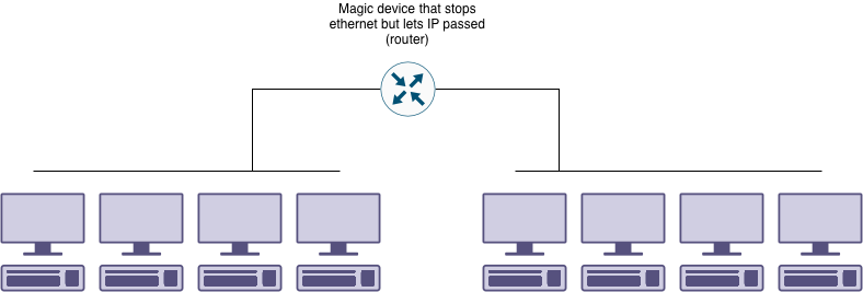
Today we’ll be focusing specifically on the layer 2 (ethernet) technical details. We won’t be talking about the security, privacy, safety, or physical reasons. There’s a lot of legacy reasons leading to cause of this, so before we dive in we need to understand some context as to why a corporate network have separate network segments and how this impacts the fault conditions we’ll discuss.
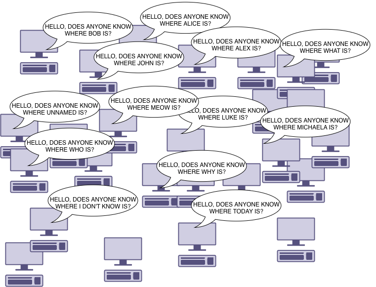
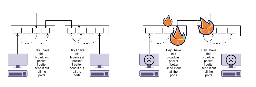
If you work in a big building like mine, or a large campus you could hundreds to thousands devices connected to the network. Devices broadcast a lot of traffic. This traffic goes to all devices. This includes working out what IP address should assigned, what hardware address maps to what IP address, and things performing network discovery so that icons pop up to indicate there’s a printer or streaming device available. This traffic is all sent to every device on the same segment. Scaling this up to thousands of devices would cause a lot of wasted bandwidth.
Even if we have enough bandwidth to handle all the screaming from devices, we still want to make sure our system is reliable. If some of the incidents I’m going to describe below happen, we want it to impact a smaller set of users, rather than the whole network.
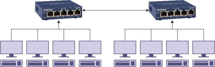
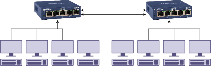
Ok. Lets start building our network. One switch can’t handle all our users, so lets go down to our local office supply store and pick up the cheapest network switch we can find.
Perfect. Then someone accidentally kicks the switch with their foot, stuff gets unplugged and there’s a rush to plug everything back in. We then end up with this.
The two switches end up plugged into each other. If you bought switches with spanning tree protocol (STP), then this is fine and will work2. If you didn’t, we end up with a loop.
What happens is the ethernet frames get sent back and forwards forever building up until there’s no bandwidth left for any legitimate data. This is why we have spanning tree protocol.
Problem solved! Just buy switches with spanning tree…. except… it’s a little more difficult.
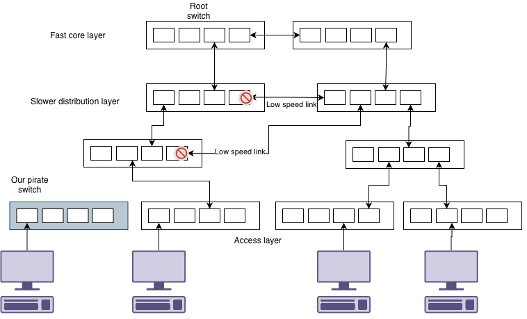
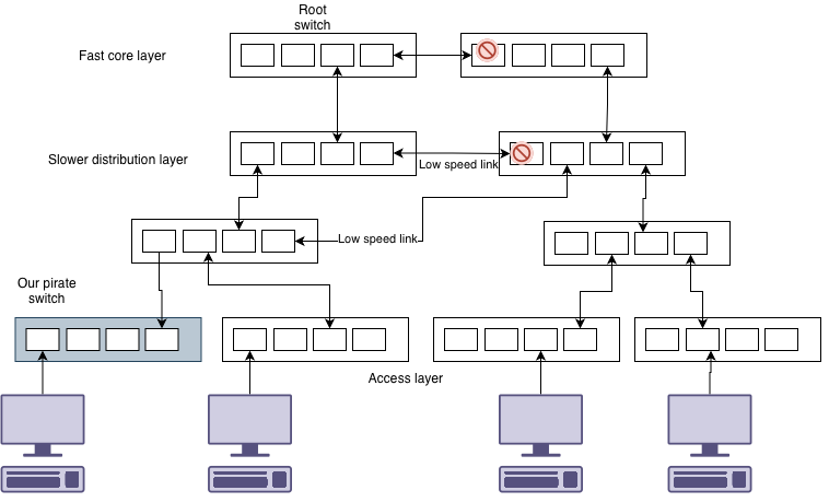
Consider this example. We add our switch into this complex network.
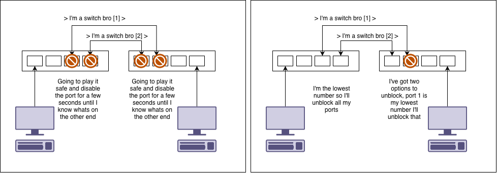
We plug in our pirate network switch. And suddenly the whole network stops for a minute or two. What just happened is that spanning tree had to reconfigure itself. This is because your switch happened to be configured with a lower priority than others and became the root switch.
You’ll notice that not only did we get hit with spanning tree reconfiguring, but also our pirate switch has forced the algorithm to select slower links than we would otherwise have available.
To make matters worse, there are multiple different types of spanning tree: STP, R(apid)STP, M(ulti)ST, P(er)V(lan)ST.
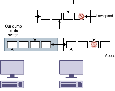
Lets go back to a dumb switch, that seems easier. What if we were to install it like above, but someone accidentally connects the dumb switch to two different switches on the network at the same time.
What happens here is that the spanning tree enabled switches can see a link to another spanning tree via the dumb switch. They aren’t aware of the dumb switch. This can cause issues like a large amount of traffic going via your tiny switch.
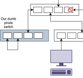
Ok. Maybe we are careful and we don’t connect another switch to ours. Someone finds a loose cable and accidentally plugs the switch into itself.
Of course we have a loop. However since spanning tree thinks everything is ok, that traffic is also transmitted to the rest of the network. From the point of view of spanning tree, there isn’t a network switch there. Even if the wired network can handle the bandwidth, the WiFi access points might not be able to.
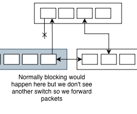
Another little quirk is that many switches are configured with a system called “port fast”. Usually spanning tree waits a period of time to figure out if there is a network switch on the other end. Port fast assumes the port is meant for a device and skips that learning/listening phase. This means that loops can exist for some time before a loop is detected. Port fast exists so that computers don’t have to wait forever to get a DHCP lease to get going.
To summarise all of this
All switches need to be spanning tree enabled for spanning tree to be effective
All switches need to be configured correctly so that the suitable paths are selected
For a stable network, switches need to be configured to prevent pirate switches
Preventing pirate switches
A number of configuration options exist to to prevent issues when switches are connected:
BPDU Guard : BPDUs are the messages sent by spanning tree. If a switch detects this on a port that has been designated as a user port it will disable the network port and requires manual reset.
Root guard : This flags which ports on the switch we expect to find the spanning tree root. We disable ports that would have resulted in a root we didn’t expect
Loop guard : Detects packet loops and disables the port
Setting low spanning tree priorities
Mac address limit : We can detect dumb switches by counting how many devices a switch port can see
Bonus 0: VLANs
How your network is configured to handle spanning tree and VLANs could be one of many many many configurations. The network might have VLANs have cover only some switches for some VLANs. Spanning tree could be running per VLAN, or a group of VLANs. This means connecting a spanning tree switch might only impact one spanning tree instance leaving loops possible in other VLANs.
Bonus 1: Unidirectional Link Detection
Unidirectional what? We like to think of network links as working or not. But there’s a secret third option - working only in a single direction. This is especially common with fibre optics and media converters.
From spanning trees point of view, it can’t see a switch on the other side and will start forwarding packets towards it, thus causing a loop. We use UDLD (Unidirectional Link Detection) to prevent this.
Bonus 2: Virtual machines
Virtual machine systems, especially complex ones, can introduce their own switching and bridging to the equation which can cause loops when trying to configure redundant links or port aggregation. They also pose other possible threats such as duplicate virtual mac addresses. Typically these will trigger the mac address limits on ports.
Bonus 999999: what about TRILL? SPB?
Network vendors don’t have your best interests in mind and decided to fuck the standards for their own vendor lock in needs.
Bonus 1000000: UniFi have a web interface to make configuring this stuff simple
So did Cisco in like the 90s. Much like UniFi it also sucked at enterprise scale.
Other reasons
So while we discussed just one technical aspect as to why just yeeting random switches into a network is a bad idea, there’s many more.
On going maintenance - firmware updates/patching
Security - if its a managed switch (common for STP support) then ensuring its configured securely
Privacy - we don’t want to open the network up to sniffing of traffic
Safety - Testing and tagging, cable tripping hazards
More technical - Sometimes what people think are switches are routers and provide a rouge DHCP server
I’m not sure if its just because they were super common or because they failed so often, but these were often found at the centre of network issues. ↩︎
Unless configured otherwise, this does not give you twice the amount of bandwidth. ↩︎