Horus 64B: What does ALSA audio have to do with high altitude balloons???
Amateur Radio Experimenters Group (AREG) decided to plan a winter balloon launch. Something that they typically don’t do due to the unpredictable weather and cloud cover.
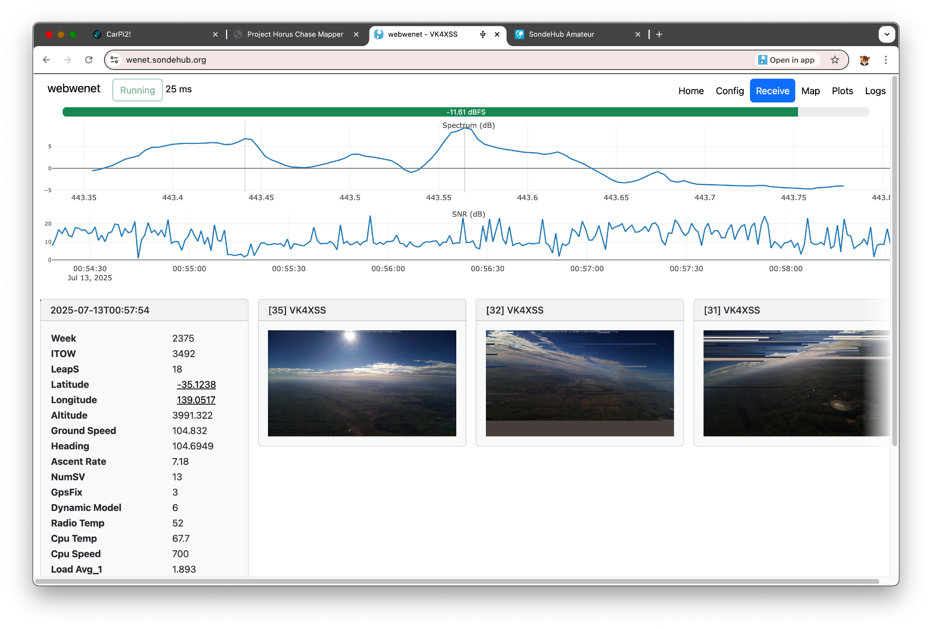
One of the ideas for the winter launch was to be a crossband FM repeater and the increased winds to Victoria would mean a larger coverage area for possible interstate communication. The other (and more interesting to me) benefit was real world testing of the webhorus and webwenet sites which simplifies decoding of both balloon protocols. While others had used the app and reported success, I had only ever tested it in my lab. It’s a bit of a weird experience to have never used my own application in a production setting.
The first possible launch date got pushed back due to bad weather. The second launch window wasn’t looking much better and if that was cancelled it was unlikely that the launch would go ahead until much later in the year.
The predictions were showing a longer distance than we could travel (legally) during the flight time - meaning that we likely wouldn’t be near the landing site on touch down. Chance of recovery would be lower.
Keen to still test my software I ask Mark if we I provided a small low cost payload if we could fly something.
I rushed together parts I had for a Wenet transmitter. Given the main payloads weren’t flying maybe I should try something a bit more experimental in nature.
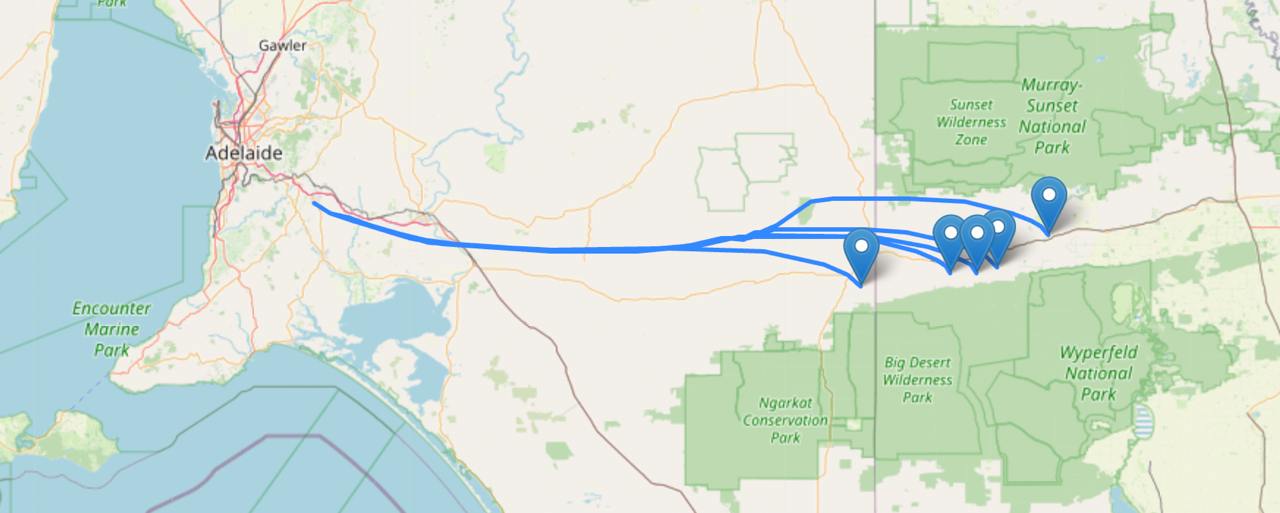
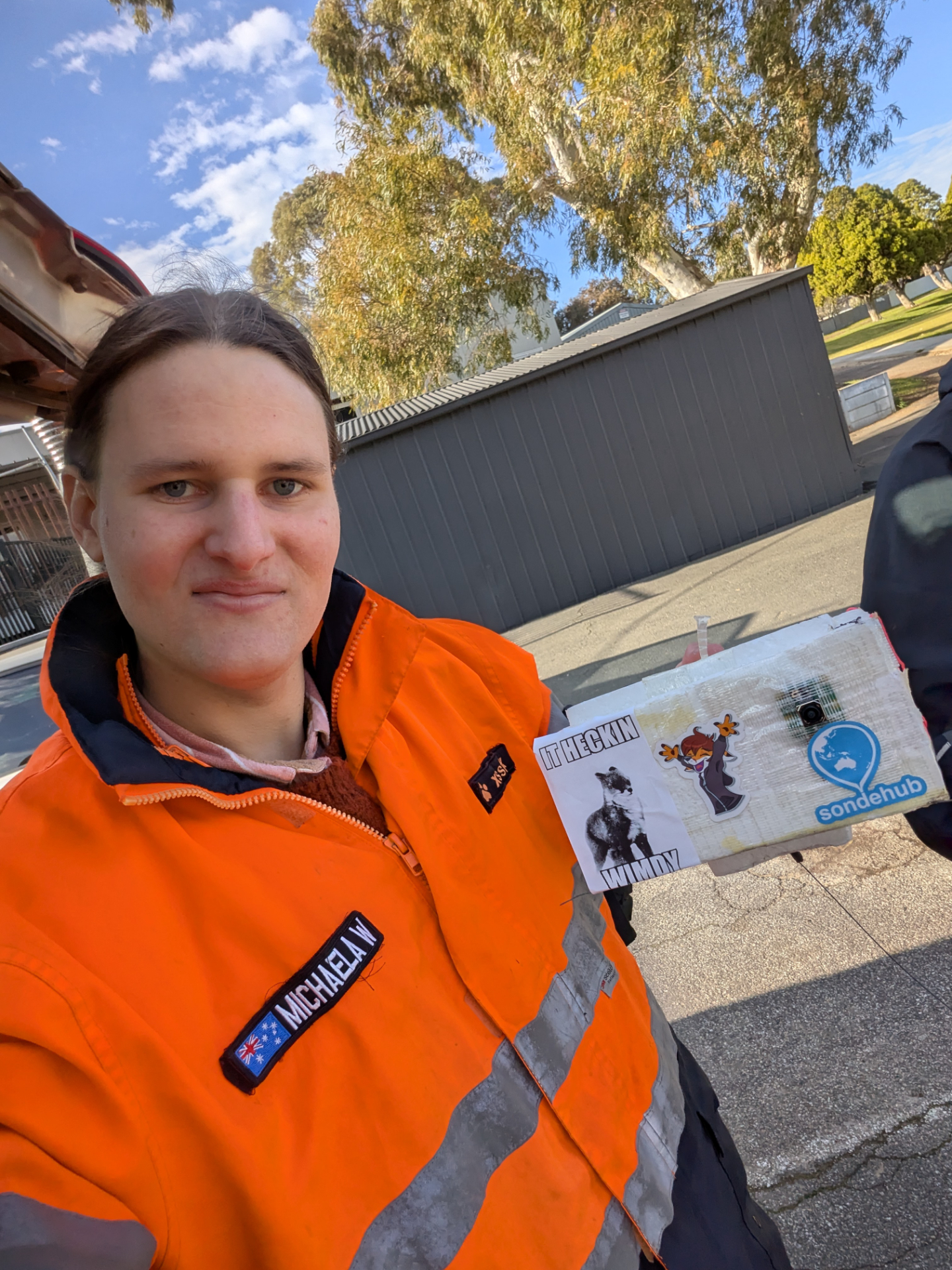
As AREG is in Adelaide and I’m in Melbourne it also meant driving the 8ish hours across. It was agreed that I would build up the Pi / transmitter and the box, antenna and camera would be installed when I arrived - leaving only a few hours in the evening for that integration to happen before launch the next day.
I2S PCM Audio
While developing webwenet I learnt a lot more about how Wenet worked. One thing that really stood out was that Wenet receivers need to remove RS232 framing from the data before decoding the packets. This initially struck me as odd. What does RS232 have to do with this protocol.
Today most Wenet transmitters use a RFM98W, usually on some LoRa shield/package. The UART pin from the Raspberry Pi is connected to DIO2. The chip is configured for a 2-FSK direct mode, bypassing pretty much all the smarts of the chip itself. If the DIO2 pin is high it transmits one tone, and if it is low it transmits the other.
Since the UART is used to transmit the packet that means that RS232 framing is also transmitted.
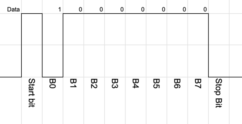
I had a quick look at the Raspberry Pi datasheet for the UART and didn’t really see a obvisous way of disabling the start and stop bits. It would be possible to bit bang data out - but timing is important for us on RF so I didn’t explore this option.
The Raspberry Pi however has a ton of different interfaces. Maybe another one would work better without the framing. My first thought was - maybe we could just bit bang a GPIO. The Pi is pretty fast and we can use some kernel features to make that work.
My next thought was along the lines of SPI, but Droppy reminded me that the Pi has I2S output - which is IMHO the classic bit banging target.
Well before the Horus flight was even planned I prototyped an I2S version which emulated the the UART (basically adding back in the RS232 framing) to compare in the lab.
Now the proper way to implement this is probably to access the I2S interface directly, however easiest approach for me to use the RaspberryPi_I2S_Master device tree driver which adds a generic sound device. This is expected to be tied to a audio chip - but we just ignore that part. From the code point of view we import alsaaudio and generate the correct audio frames.
Some complications show up though. The linux simple-audio-card driver seems to have fixed set of sample rates and channels. I don’t think there’s a specific reason this needs to be the case, but without building a new kernel module it means a little bit of extra work. Now channel wise it doesn’t matter so much, we send the samples irrespective of which channel is selected (that pin gets ignored entirely) - but we do have to factor the channels into our data rate.
So with only hand full of sample rates to choose from how do we get the bit rate we desire. At startup we calculate the desired RF bitrate and then work out multiples of the audio sample rates.
For example - if the audio sample rate is 48000, the number of channels is 2, 16 bit audio width and the desired RF baud rate is 96000, then the audio bit rate is 1536000, then we divide by 8 bits per byte - 1536000/8 = 2 bytes. So for every “1” bit we send two bytes - 0xffff and for every “0” bit we send 0x0000.
In testing however I noticed that my transmitter just wouldn’t work when running the software. It turns out the Wenet TX software had an LED configured for the same GPIO that was used for I2S PCM out on the Pi. Annoyingly when this GPIO is set the Pi had to be rebooted before the I2S output would work again!
To make use of the advantages of I2S approach I needed to write new transmitter code which didn’t include the RS232 framing, update the existing Wenet receiver software, and my webwenet code. This was a big undergoing so close to the flight deadline, but we managed to do it.
By removing the RS232 framing we remove the 20% overhead from start and stop bits. This allowed us to pick a lower RF bandwidth while still being slightly faster than the original system.
Modulation testing
It’s all fine doing this in practice and testing locally where SNR is high, but we need to make sure that both the modulator and demodulator is working correctly. Subtle errors in things like the parity code, timing mistakes or off by one errors won’t be apparent until low SNR.
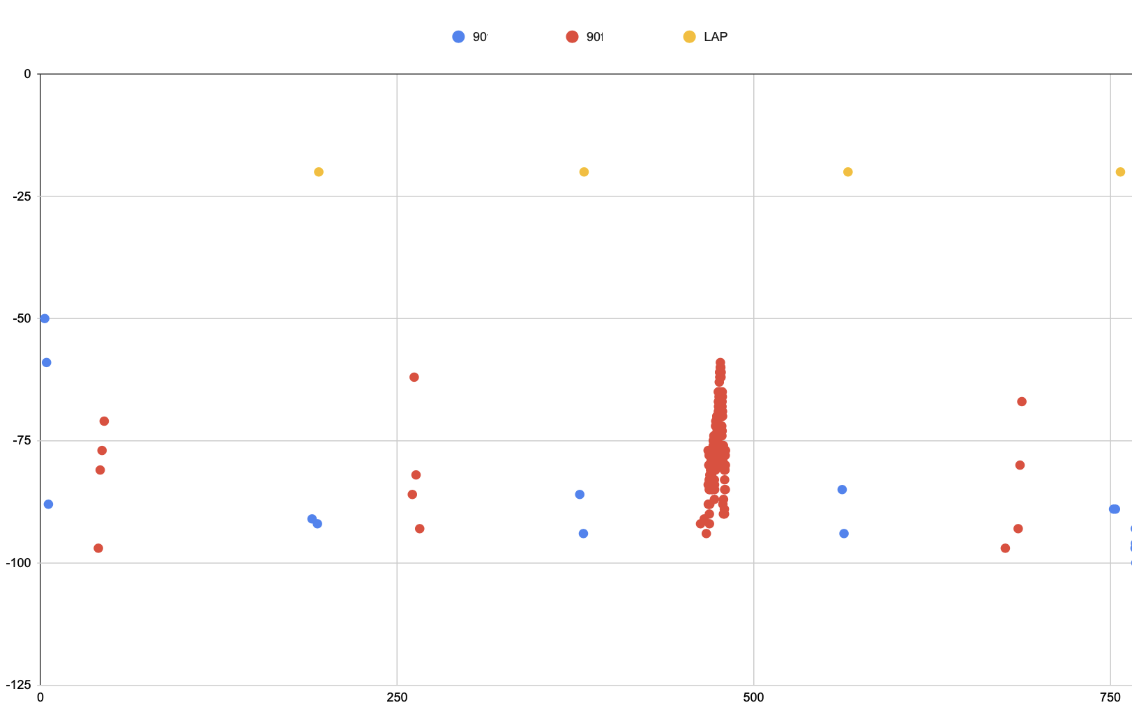
To do this Mark built some benchmarking scripts. These take a high SNR recording, then generate lower SNR samples. The lower SNR samples are feed back into the demodulator and a count of the packets decoded is taken. With the low density parity check (LDPC) and the quality of the modem we expect a fairly sharp fall off. The nice thing about these scripts is that they normalise for Eb/N0 (SNR per bit). This means that even though our baud rate is different we can still compare the new I2S method to the old UART method.
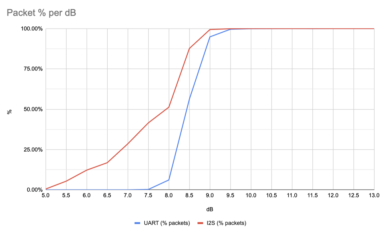
When we run this I2S we see similar dB threshold where all the packets are received however there’s a bit of a weird slope. We expect that due to the parity check that either you receive a packet or don’t, so the dB difference between that threshold point should be small. This lead us to believe that the testing wasn’t working right.
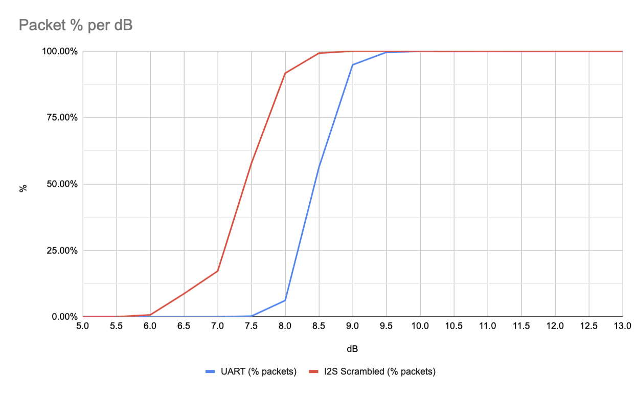
Now one thing that we noted when switching to I2S is that the UART method didn’t include any sort of scrambling or whitening. Scrambling is used to ensure that there isn’t a long run of zeroes or ones which could cause the modem to loose timing and become unsynchronised. For the UART mode this wasn’t a big concern because the RS232 framing meant that the start and stop bits would always cause a 1 and 0. Switching naively to I2S meant that we lost this free bit flip.
The theory I have at the moment is that the long runs of 1s or 0s in the I2S approach breaks the normalisation scripts. Adding in scrambling we get a much sharper cut off as expected.
Dual mode
While I was pretty confident in the I2S approach we wanted to be able to compare the two modes in a real world setting. A normal person might just fly two payloads or have two transmitters. Instead however I decided that it was likely possible to have the software switch between the two modes.
To do this a soldered diodes to the output pins on the Pi and feed both UART and I2S to the RFM98W module. With the hardware done, we need to look at the software. The first problem is that the UART transmitter needs to disable its output when its not active. To do this we use the break_condition attribute in pySerial. I2S luckily sits low normally so nothing needed to be done there. Finally we need to switch between the two modes in the transmitting software - which it was never really built for. I hacked in the functionality to have a list of radio modules which are cycled only when the radio is in an idle state after a period of time.
The result was that the radio switched between modes roughly every 1-2 pictures.
Testing deadlines
I moved my code over to the target Pi Zero 2 W. Went to plug in my PiCam only to find the connector is different between the Zero and the normal Pi. From a “launching the balloon” point of view it wasn’t going to be a problem as the camera was being supplied by Mark however from a testing point of view it meant I wasn’t going to be able to test that the camera functions. I rushed off an order to Amazon for a camera module that did have the correct cable.
In the meantime I tested without the camera module. I had some extremely weird issues. File descriptors were being opened and after about an hour the software would crash due to reaching the ulimit. Debugging the issue and I couldn’t determine what was causing it - I thought it was caused by swapping between the two radio modes, but that didn’t seem to be the case.
I tried a bunch of Python debugging tools to see the cause but couldn’t nail it down to any Python code. It seemed to be occurring due to the picamera2 Python module. It seems that file descriptors were being leaked due to the lack of camera connected - but I wasn’t entirely certain. To alleviate the problem I bumped up the max number of files open in ulimits however it turns out that select is limited to 1024 file descriptors anyway - so that option didn’t work.
I quickly added a shell script to check for open file descriptor count and put into the watchdog.d config. If it got too many fds it would reboot and everything would be fine. It’ll do.
Integration woes
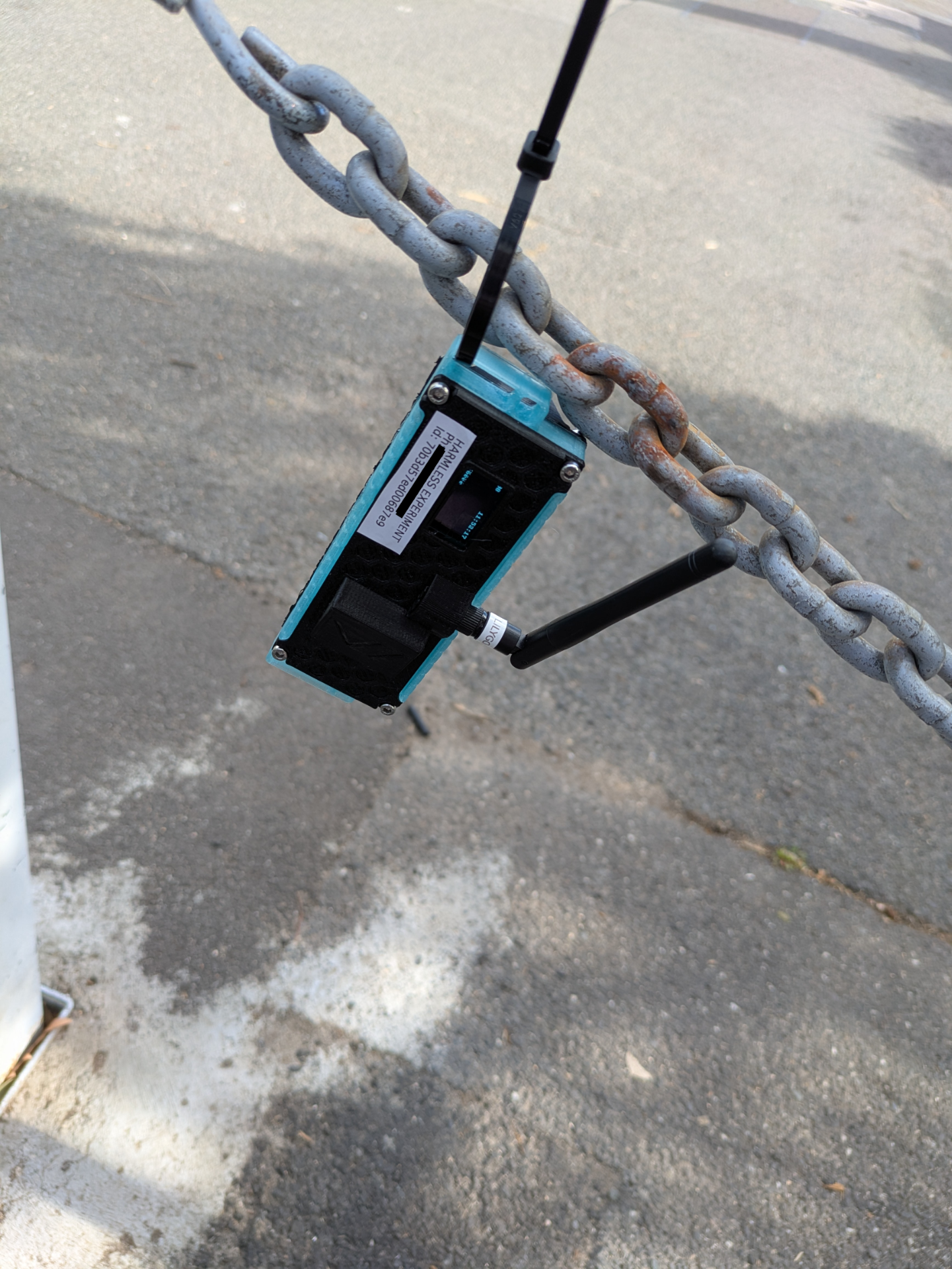
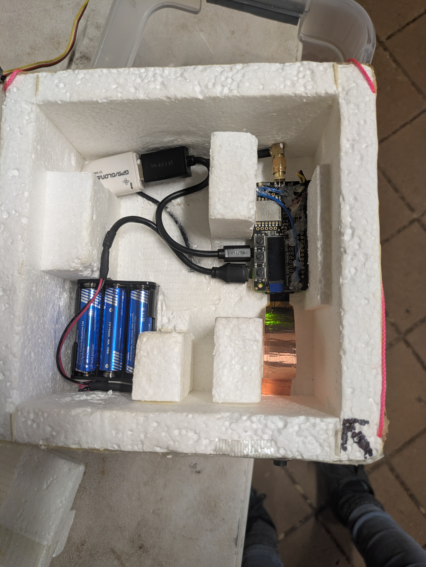
Arriving in Adelaide I passed the payload to Mark who quickly fitted it into the box, added the camera and we fired it up.
Two issues presented us. The GPS didn’t stay locked / struggled to lock. I had seen some of these issues with my testing - we’re not entirely sure why my uBlox 6 chip wasn’t working correctly as ubxtool showed correct data. Current suspicion is that the code was written for uBlox 7 and isn’t happy with some of the data. The other factor is that I was using soft serial (as UART was taken for I2S transmitter). After some quick debugging we opt’d for replacing it with a known good USB GPS module.
More concerning was that with the new camera connected the Pi rebooted shortly after initial boot up. We believe this was a kernel panic but with no swap setup to do coredumps we don’t really have any logs of that. I believe this was to do with the PiCamera 3 module as I didn’t see the reboot happen in my testing.
The reboot didn’t happen often and the system started up again just fine. But it’s not something I really like to see before launch. The picamera2 github is full of issues of people having random issues with the library. I even saw some issues where Python crashed somewhere that it practically couldn’t, and I think this was also caused from the picamera2 library - my guess is that it lacks thread safety and incorrect/lack of locking.
I put in some extra error handling. We did a few tests and it seemed fairly stable, even if it did reboot. However it exposed a known limitation in webwenet. Wenet protocol sends images with a byte for image header, followed by a byte for an image id. Restarting the payload resets the image id. When webwenet receives an image is combines all the packets for an image based on the image id. With the image id reseting the images were being updated rather than replaced in the UI. So a last minute patch/hack was added so that users wouldn’t get confused if the image id was reset.
Launch day
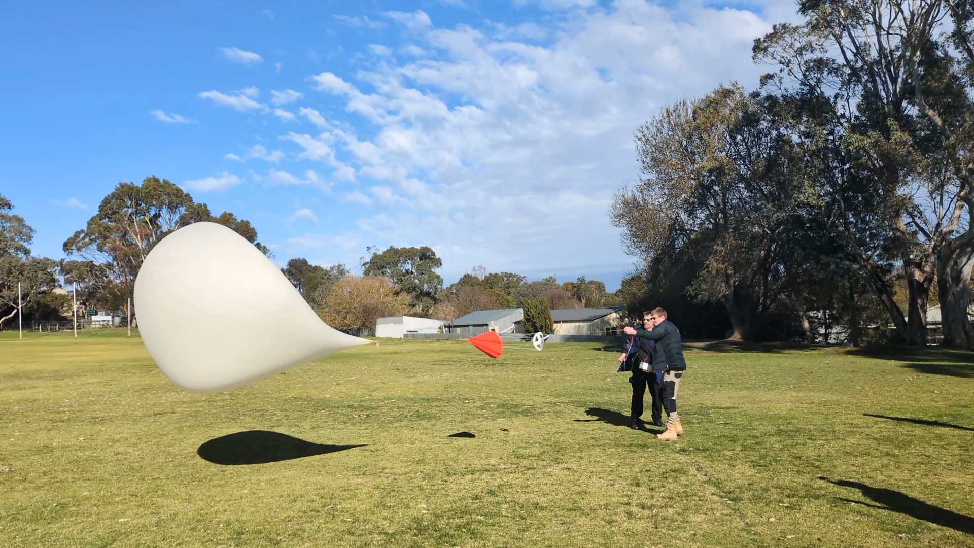
We arrived at the launch site. The car was prepped for receive mode and the balloon was filled. Up until now we hadn’t really decided if we wanted to chase the balloon, or if we wanted to get to a higher location to have a better chance of receiving as much data as possible. We opt’d for the high location and would attempt recovery on our drive home the following day.
Many hands were required to handle the balloon during filling and tying off, but eventually it was filled and launched.
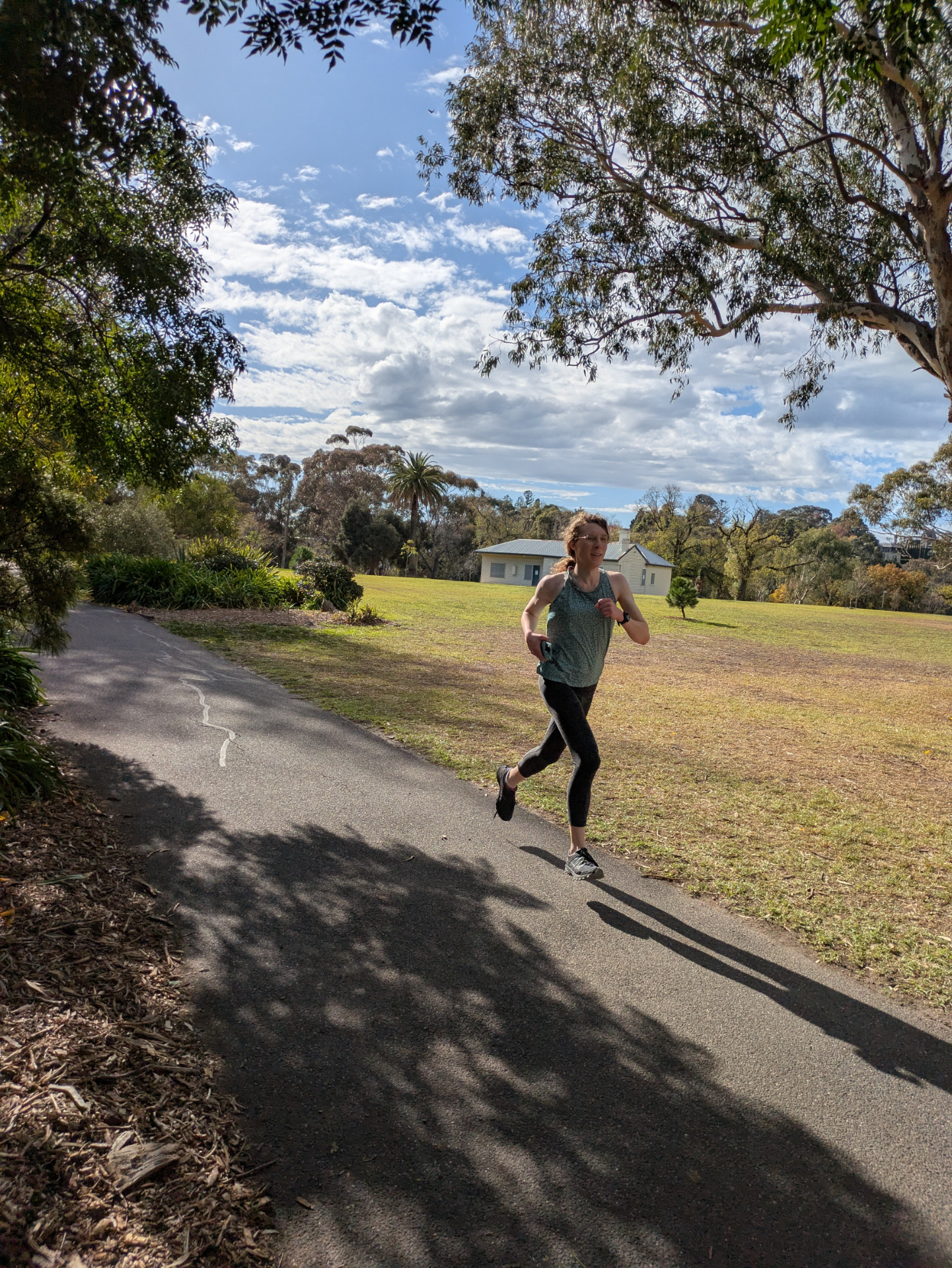
Droppy drove while Alex and I monitored the balloon and receivers. One of the things I wanted to test with webwenet was around lowering the entry requirements for receiving. What would be the minimal equipment needed to receive?
For that I went with:
- LNA4ALL - €23 + shipping
- RTL-SDR $33.95 USD
- AliExpress 7 Element Yagi - $93 AUD
- AliExpress 3dbi “short” vertical antenna - $15 AUD
The LNA4ALL was chosen as it can be powered directly from the RTL-SDR using the Bias-T option. The LNA4ALL does need a small modification to allow this.
I created a few little brackets for our cars roof rack that mounted the LNA close to the antenna.
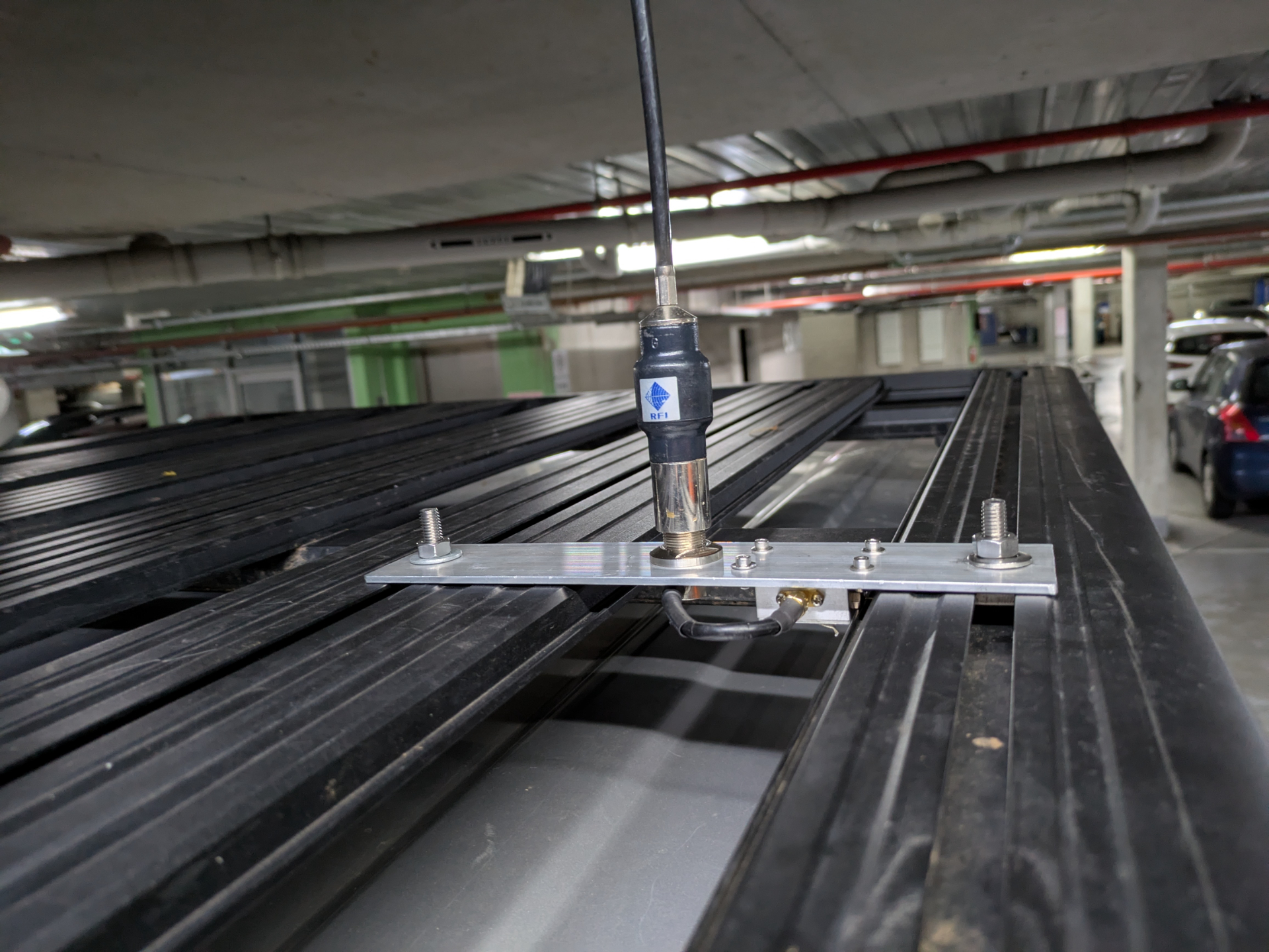
The small vertical antenna is used while driving as it provides low gain. A higher gain antenna would result it a more narrow beam which isn’t very useful if the balloon is high up.
Once we arrived at the high location we switched to the yagi antenna which provided a reasonably good SNR throughout the rest of the flight.
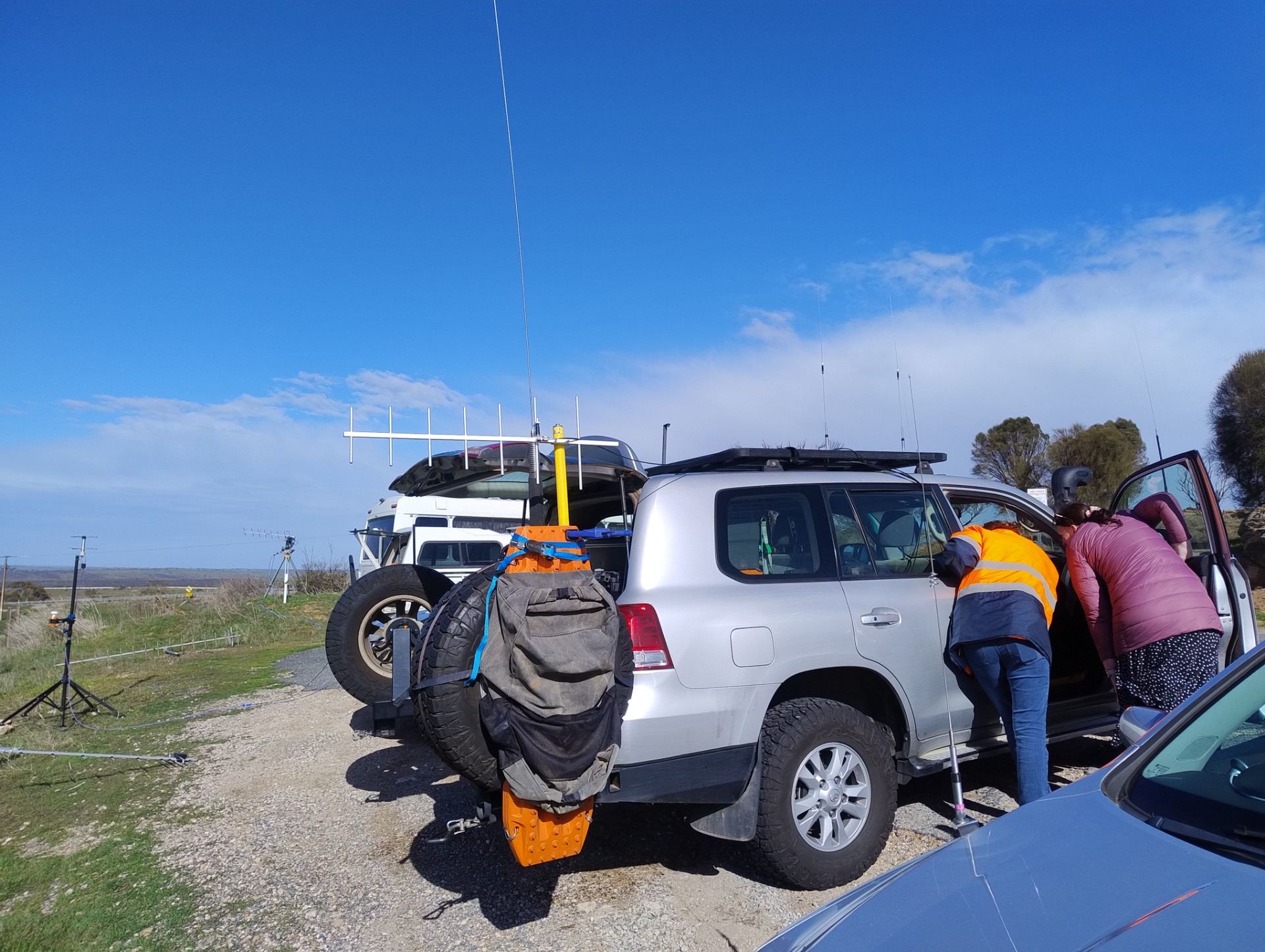
This setup worked fairly well and was pretty on par with some of the bigger setups we saw on the day.
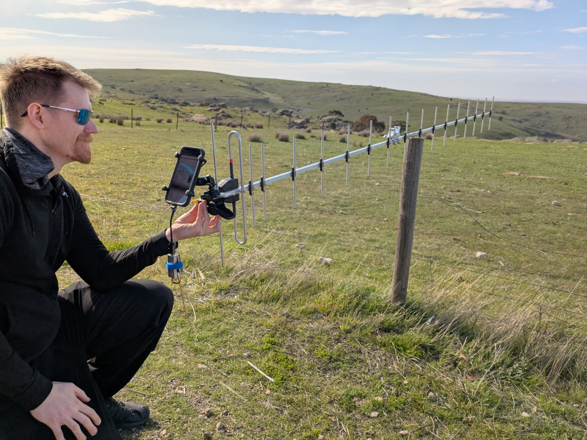
Fun with phones
One of the fun things with webwenet and webhorus is that you can load it up on mobile phone browsers. This meant that we hooked up a mobile phone on a many-element yagi - something that just seems extremely ridiculous.
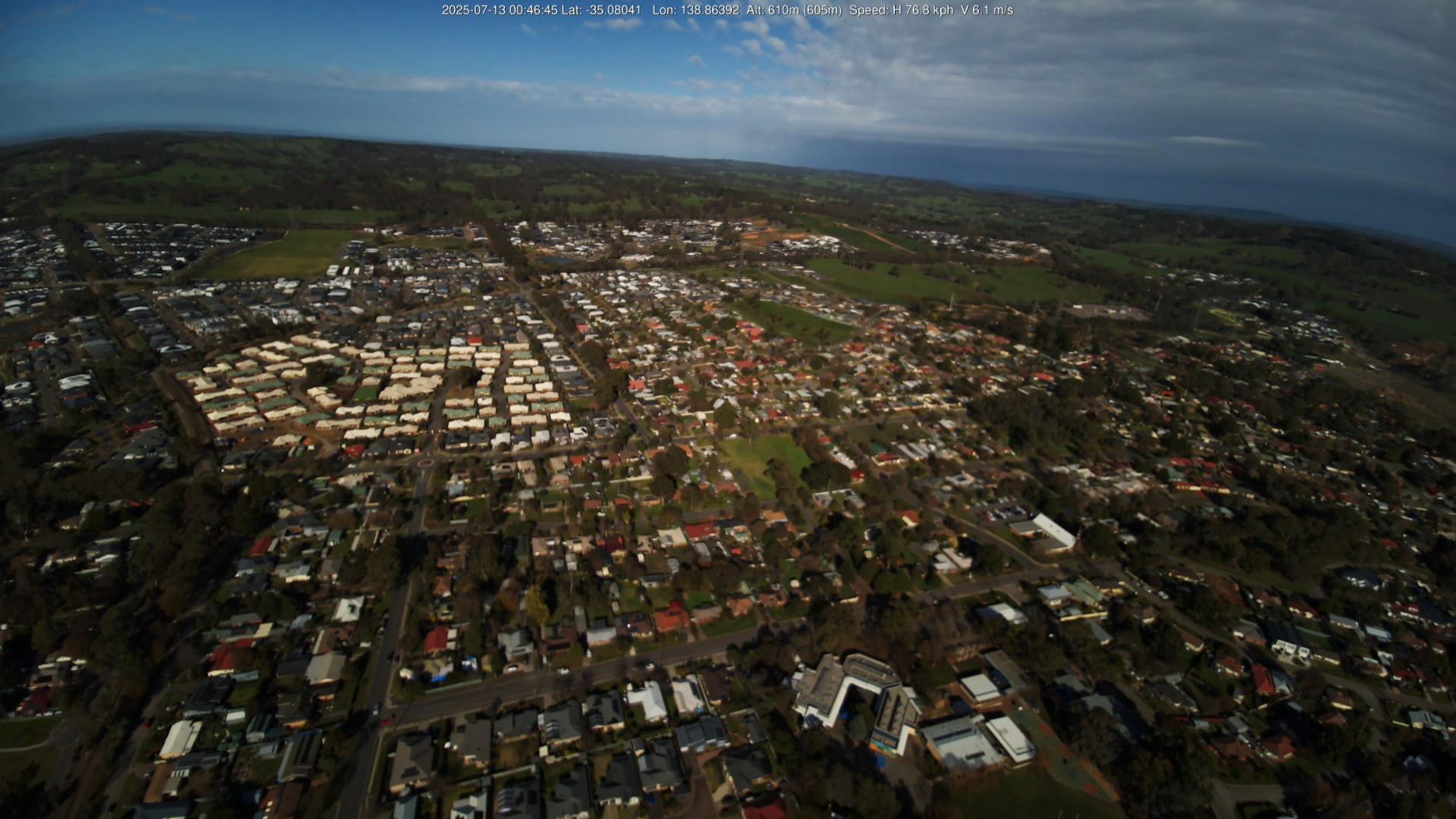
Pi Camera 3 Focus issues
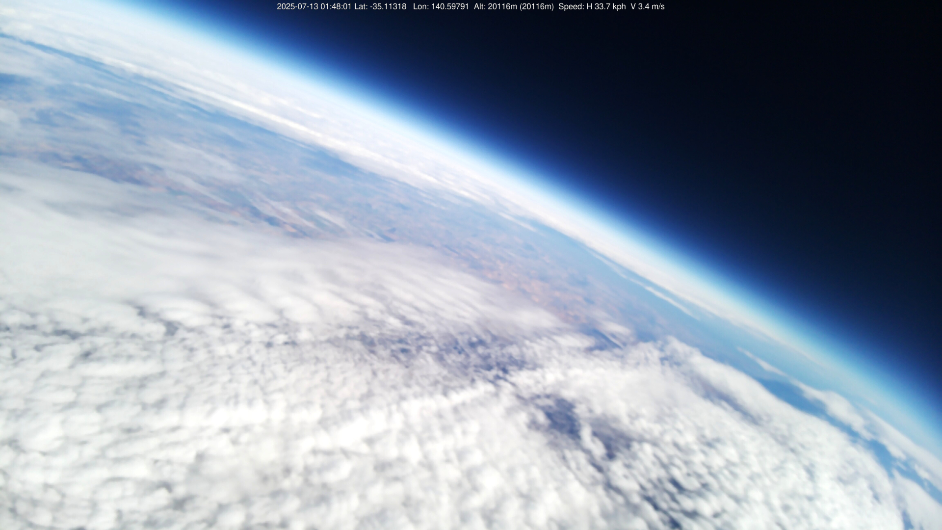
As images started streaming in it was obvious that a long running issue with the Pi Camera 3 had struck us. Out of focus images. Current suspicion is that the payload is moving too much for the Pi Camera 3 to obtain proper focus. Which is a shame because some of these pictures would have been stunning. Regardless I still think they look pretty good.
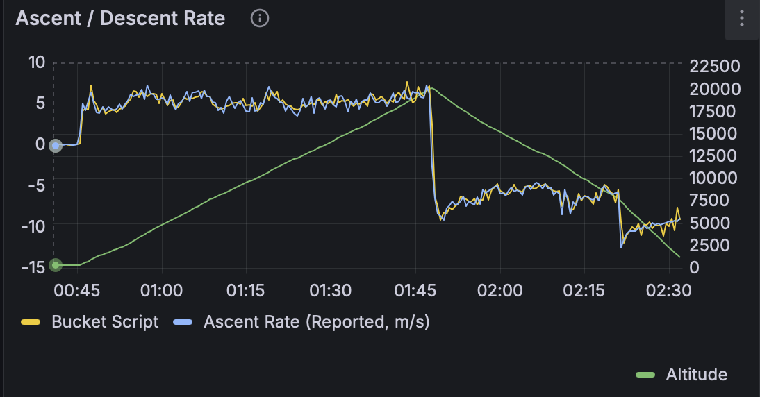
The highest picture was recorded at 20,116m.
Landing and recovery
The balloon landed over 250km away. The last reported altitude was 1,083m.
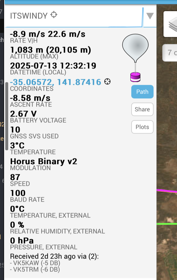
Being so high up for the last reported location leads to a very large search area. Local ground winds play a huge part in final landing location, so it was going to be a challenge to recover. Probably unlikely given that the transmitters batteries would now be flat and uncertainty regarding if the balloon still had a red parachute to spot.
Arriving at the predicted landing spot, the farmland covered the repeating dunes. Luckily being winter the fields were bare. We stopped on the second dune near our suspected landing location and walked across to the next. Not even sure which field it had landed in we kept scouting around. Part way up the next dune I spotted in the distance a red patch with two white items near it. It was a long way away but given it was unlikely that the field would otherwise have something like that in the middle of it I was pretty certain that it was the payload.
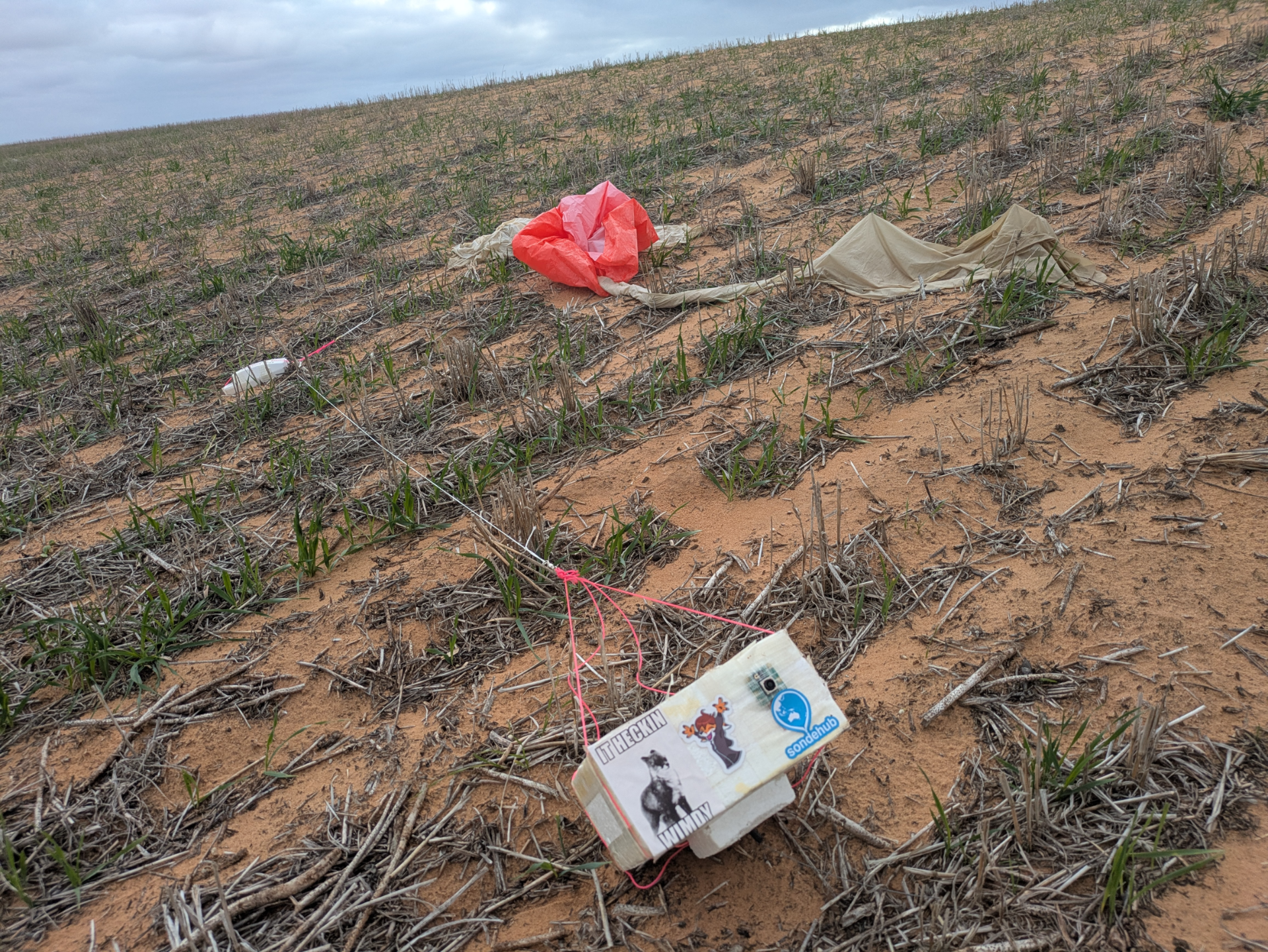
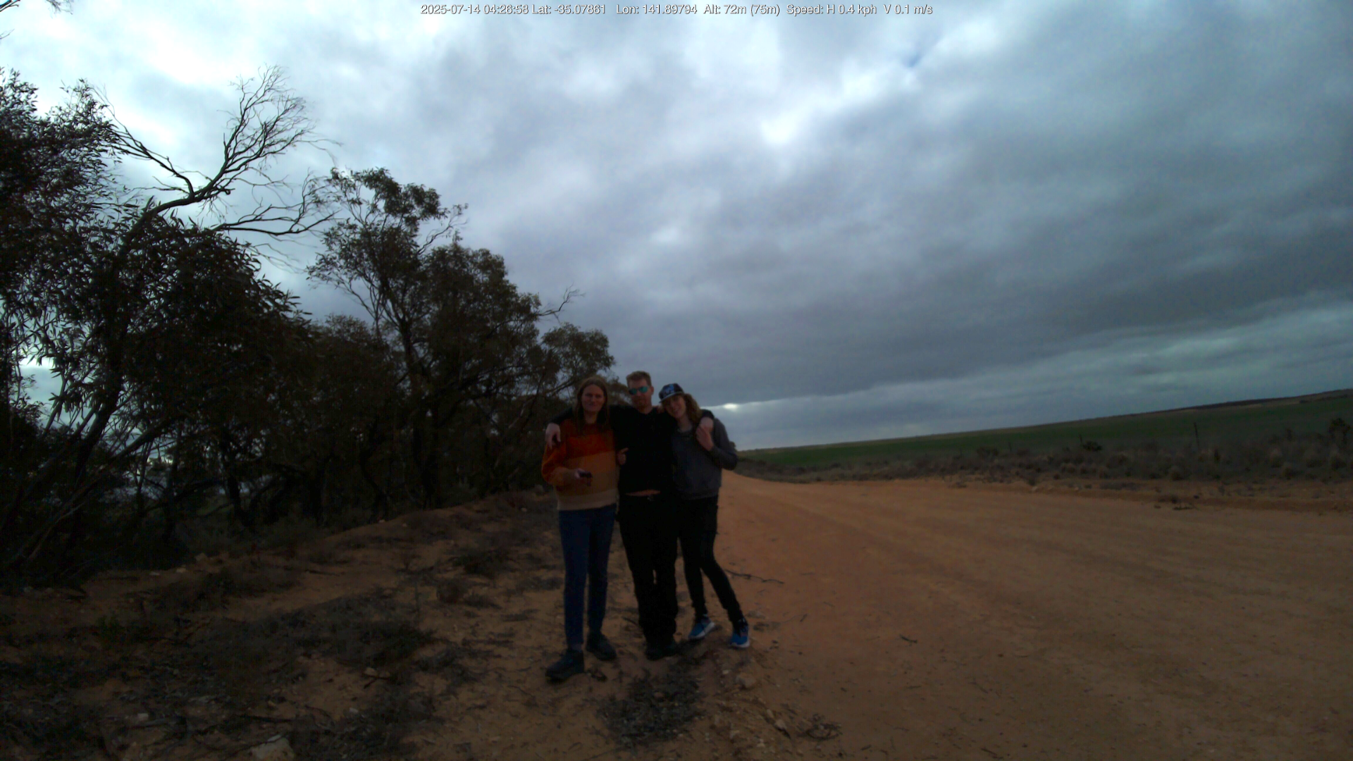
Walking across the field I arrived at the landing site. It was a surprise to recover the payloads with the data we had, let alone find them so easily. I guess one advantage to winter launches is empty fields. Enjoy the time lapse created from the remaining battery on the image transmitter payload.
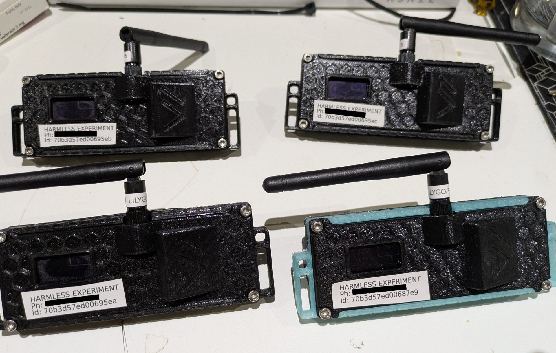
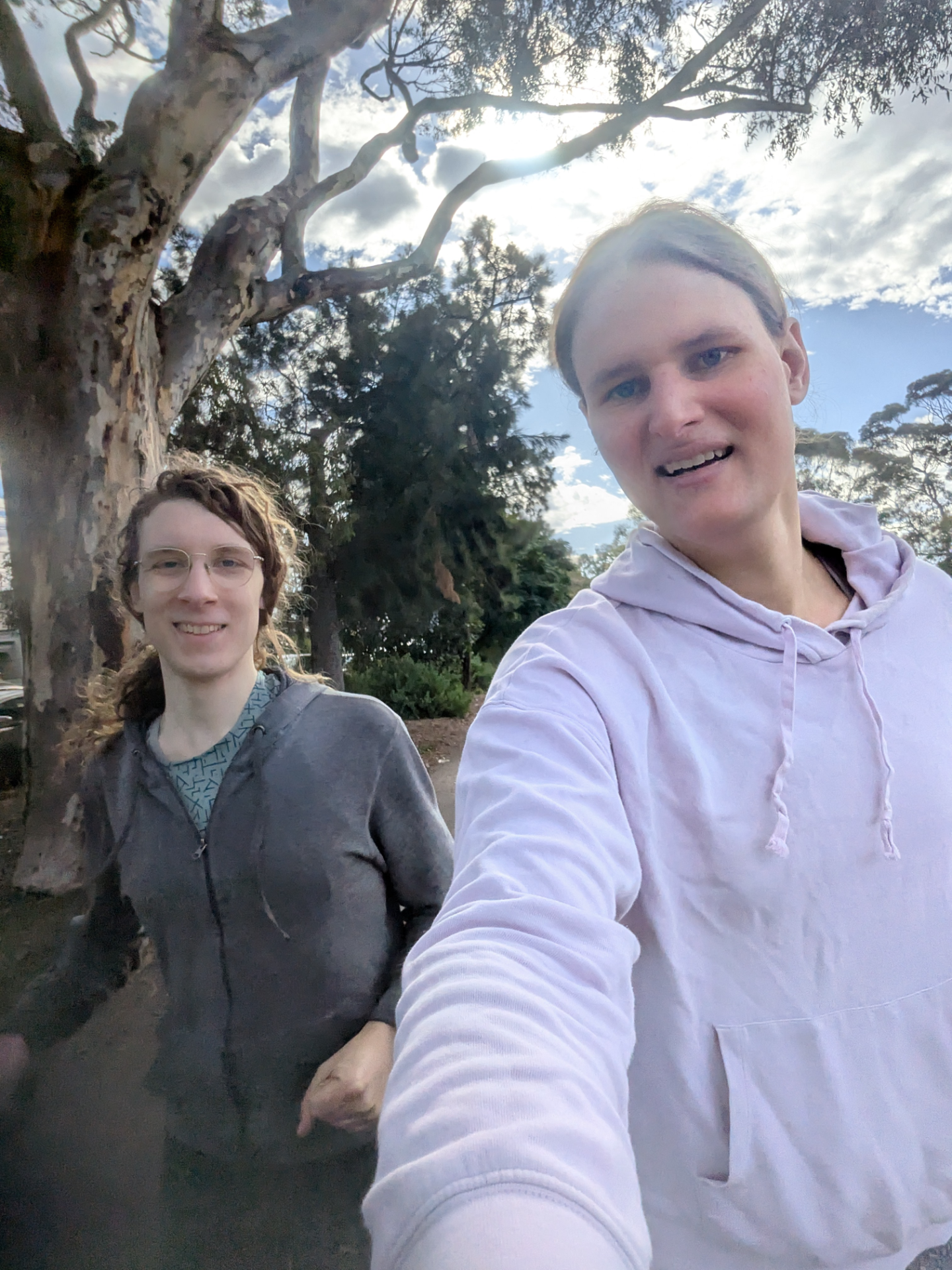
After bringing the payload back we opened it up and turned it back on to get a group photo before heading back home.
The final verdict on I2S
It performed no worse than the UART version. The theoretical performance increase of the lower RF bandwidth requirement isn’t actually much - to the point that it’s in the testing noise. We do know that the data rate is slightly faster though. The other advantage is that it frees up the Raspberry Pi hardware UART for other tasks. It sounds like AREG will be flying I2S Wenet going forward after the success of the dual mode payload.
Thanks
Many thanks to AREG, Mark, Droppy, Alex and all the receivers who let me fly this payload, help with recovery and put up with my bullshit.