Caution. Using traffic preemption devices such as described in this blog post could impact emergency response times. The use of these devices outside their approved use may be illegal in your area. Traffic light preemption systems are typically logged and intersections often have video recordings. Traffic lights might not respond how you expect. All information in this blog was derived from reading manuals and testing in a lab.
Additionally - I’m not an expert in this field. I don’t maintain emergency vehicles, traffic controls systems or have any formal training. This is just me vomiting up information I read.
Say you are an paramedic and the patient in the back of your ambulance is leaking all the human goo required to keep them alive. Alternatively you can be Karen in the family SUV taking your 2 kids to band practice 600m away from home. Between you and success are 18 thousand traffic lights and 2 million vehicles because of car centric design. It would be great if in emergencies (like being late to band practice) you could magically control the traffic lights to give yourself all greens.
This is what traffic preemption is. For emergency vehicles this is usually called Emergency Vehicle Preemption or EVP. There is also Transit Signal Priority, TSP, which is used for mass transit such as buses and trams.
There’s many different systems for EVP and TSP. We’ll be looking at just a single type in this post, but first I want to explain some of the hidden complexities in these systems. Obviously we want to turn the light green when there’s an emergency but whats involved with that.
- First the driver of the vehicle needs to declare an emergency - we don’t want every off duty emergency vehicle stopping traffic lights
- Then the traffic lights need to know there’s an emergency.
- Specifically, the set of traffic lights that the vehicle is driving to - we don’t want every set of traffic lights to change in the city
- The traffic lights themselves also need to know where the vehicle is coming from. We want all greens, not all reds
Before the days of super reliable vehicle positioning solutions, this was a bit of tricky problem to solve. Additionally, not all traffic lights are wired up to a central location. Some solutions involved directional antennas. Some systems tried to identify strobing lights. While there have been several solutions to this problem, the one that really won out in the 90s and 2000s was infrared. It might be a bit of a surprise to think that the principals behind a TV remote ended up as critical infrastructure.
Infrared works really well in this use case as an emergency vehicle can flip a switch (maybe its just wired to the same one as sirens). The emitter can be placed on the roof of the vehicle and pointed in the forwards direction. At the traffic lights several detectors can be placed facing various directions of traffic flow. An optical signal processor will receive the data from the detectors and determine which cycle the traffic lights should switch to.
Ah, so the Flipper Zero can control traffic lights?
At this point in our story. Maybe. There are several videos on YouTube, forums and social media sites claiming this. The thing is, it’s very very very easy to fake a video like this. Wait for the traffic light cycle to just about start - hit the button, look amazed. At the same time, it does actually work…. for some traffic lights.
Some systems have confirmation lights to let emergency services know that the signal worked - though I haven’t seen many of these in practice. A good way to confirm if these videos are real is checking for these confirmation lights.
The early implementations of this infrared detection system used IR pulses at 14.035 hz. The Flipper Zero can likely replicate this just fine. For transit priority this is usually lower, like 10hz, 9.something or 6hz.
Obviously having people mess with traffic lights using an IR LED and a 555 timer is not a good thing™. So both GTT (3M at the time) Opticom systems and Tomar Strobecom implemented different ways of encoding data into the signal. Not only did this allow for security, but allowed extra functionality like deciding which vehicles get priority over others and opening gates. Of course these two systems are patented and each company even has patents on how they could interoperability, ffs. GTT and Tomar also got into a patent tiff with the two settling out of court. I love when emergency/critical infrastructure is locked behind patents and trade secrets.
We’ll be talking about the Tomar Strobecom system, however the briefly before that, lets take a quick look at the GTT (3M) Opticom system. Through eBay (which doesn’t actually permit selling these devices) I was able to obtain a “Tomar 970APRE-PS-T792” power supply. This might be confusing you as I said GTT system, along with this is the power supply, not the emitter.
Tomar uses Xenon flash tubes to generate the IR signal. The emitters in the Tomar system are actually just the tubes. The logic/smarts happens in the power supply. Tomar sells a range of devices which are compatible with the GTT system and this power supply is one of them.
I hooked this unit up to my scope (noting that since we are dealing with possibly kilovolts here we need to be careful…) and recorded a capture.
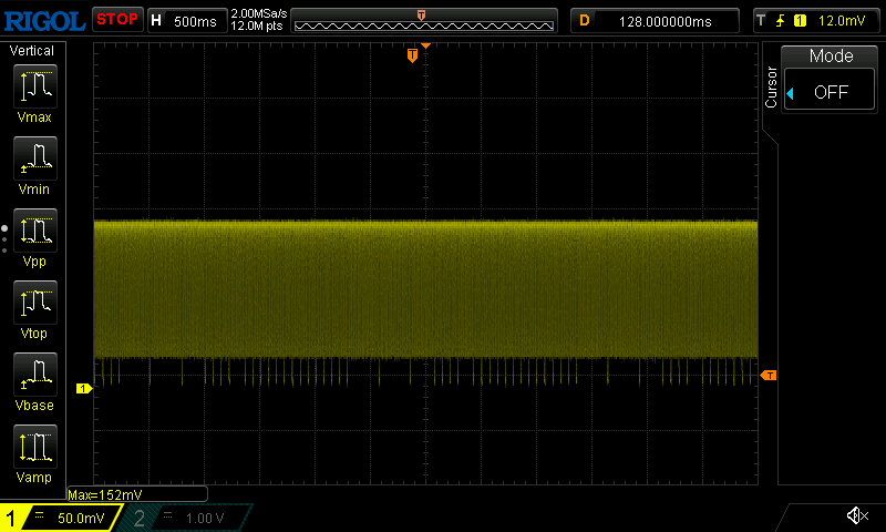
In the GTT system you can see that the data is encoded by skipping bits. Something that the Flipper Zero could do if you recorded one of the signals of a configured vehicle ID.
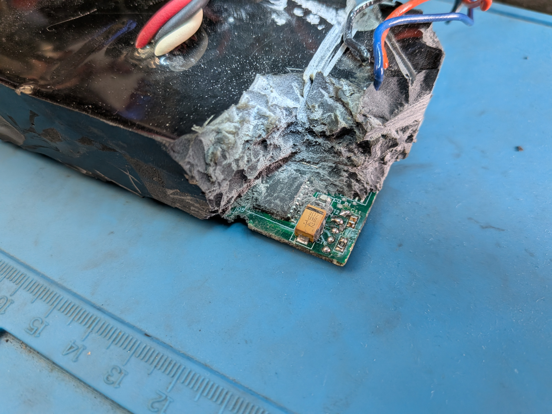
I also went through the joy of de-potting this power supply. Unsurprisingly its a PIC16F628. I believe I can change the ID of this unit, however I haven’t figured out how yet. I believe it’s via J1708/J1587 - it’s also possible I killed it during de-potting…
Why do I care about the Tomar Strobecom II system so much anyway?
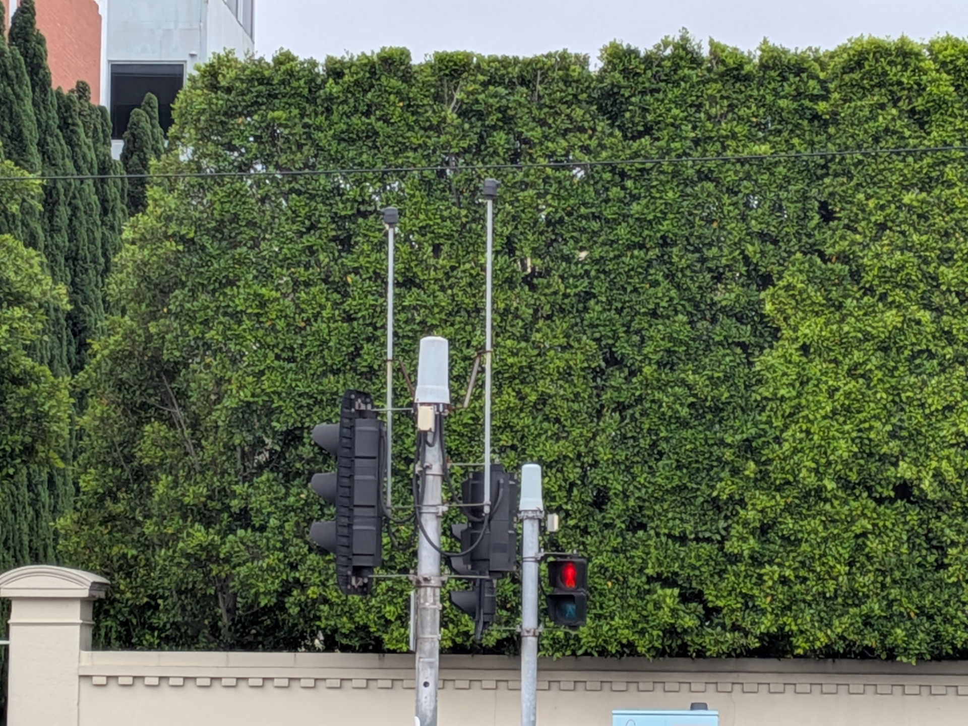
Well mostly because I wondered what the little Strobecom II detectors were on traffic lights. I came across VicRoads TCS 055-1-2005.
2.2 SYSTEM SECURITY The EVP system shall be a secure system that prevents false activations, unauthorised activations and ‘hacking’.
Games on.
The other reason is many government tender and policy docs specify things like:
be a Tomar® 2140 Optical Signal Processor or similar, fully compatible, processor
Without knowing how these systems work, it’s impossible to building a competing product that would meet the tender requirements, even ignoring patents issues. And I think thats a problem when we are talking about critical life saving infrastructure. Lower cost can mean more installs.
Quick note around Victoria’s EVP system: The TCS 055 copy I have is dated 2005. When observing vehicles today, I see very few with EVP emitters installed and I haven’t managed to capture a real world sample of the signal they emit. My suspicion here is that the Strobecom system is no longer maintained and that GPS / radio based system is used instead. This is just speculation however.
So what do we know about the Tomar Strobecom II system?
We know:
- it’s not the GTT system - so likely isn’t using missing pulses to encode data
- the emitters are Xenon tubes not LEDs - so bursts of data is unlikely - additionally the Tomar system is specifically designed to require a max of 10 microsecond rise time for the pulses (according to datasheets)
- the emitters will likely still be detected by legacy 14.035hz systems
This a bit rough to work with, but we can get some extra clues from patents.
- US5519389A “Signal synchronized digital frequency discriminator” is Tomar’s key patent for Strobecom - effectively showing that Tomar can check the timing of pulses
- US7417560B2 (and a few others) “Multimode traffic priority/preemption intersection arrangement” from 3M mentions how the Strobecom II system uses variable length delays between pulses to encode data. Annoyingly it doesn’t mention how long, or the format - but its a hint.
Recording pulses
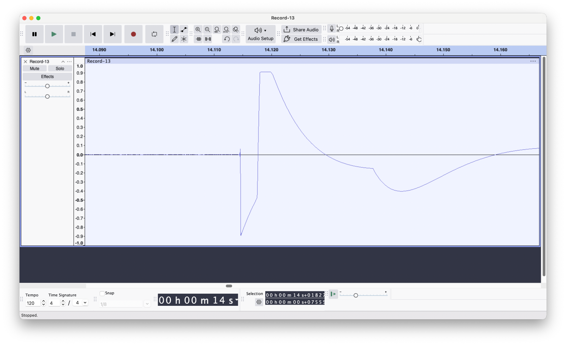
My next thought was, why don’t we just record some. I built this little detector using a Pixel headphone/microphone adapter, wired an IR photodiode in series with a resistor across the microphone and ground pin.
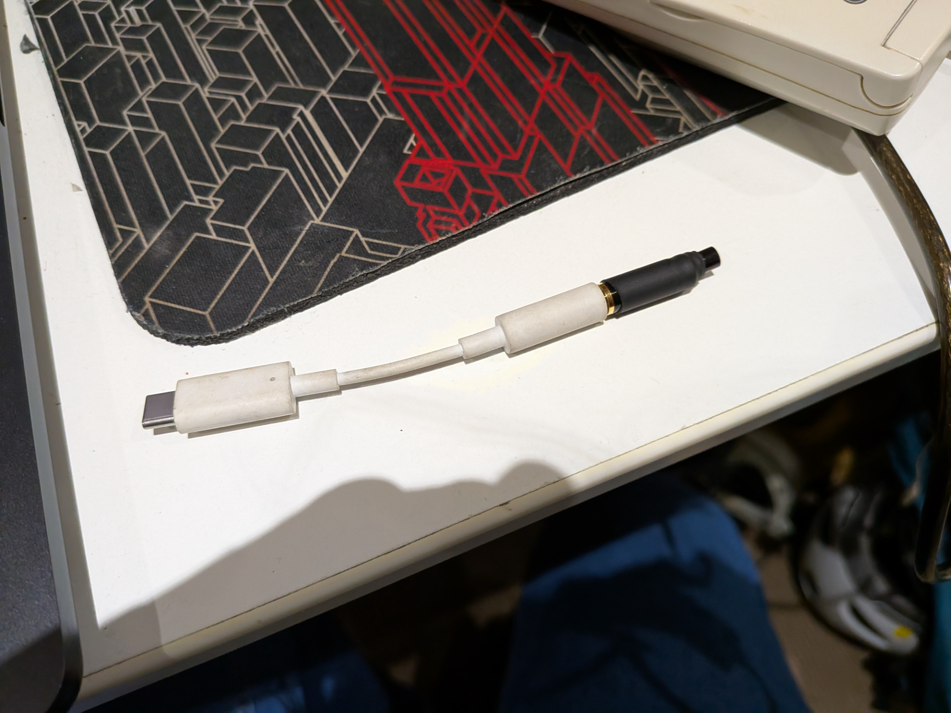
I then tested with a camera flash - and sure enough it recorded the pulse. I was probably a bit too close to the photodiode and the signal went straight into clipping. But that’s ok.
As mentioned above however, the Strobecom system is less widely used in Victoria than I first thought, so even though I have recorded several passings of lights/sirens vehicles, none of them appeared to have Strobecom running/installed. (Annoyingly I’m pretty certain there was one emitting just before I built this device).
Sit at traffic lights and try all the combinations
Just kidding. No ones taken away my eBay account yet so I bought my own Tomar Strobecom 2140 Optical Signal Processor (OSP). The same one listed in the VicRoads specification. This was a bit of a risky purchase because at this stage I didn’t know how much smarts were in the detectors vs the optical signal processor. It’s possible that the detectors decode the ID and just pass it to the signal processor… Ideally I would have purchased detectors as well, but those were on the much more expensive side.
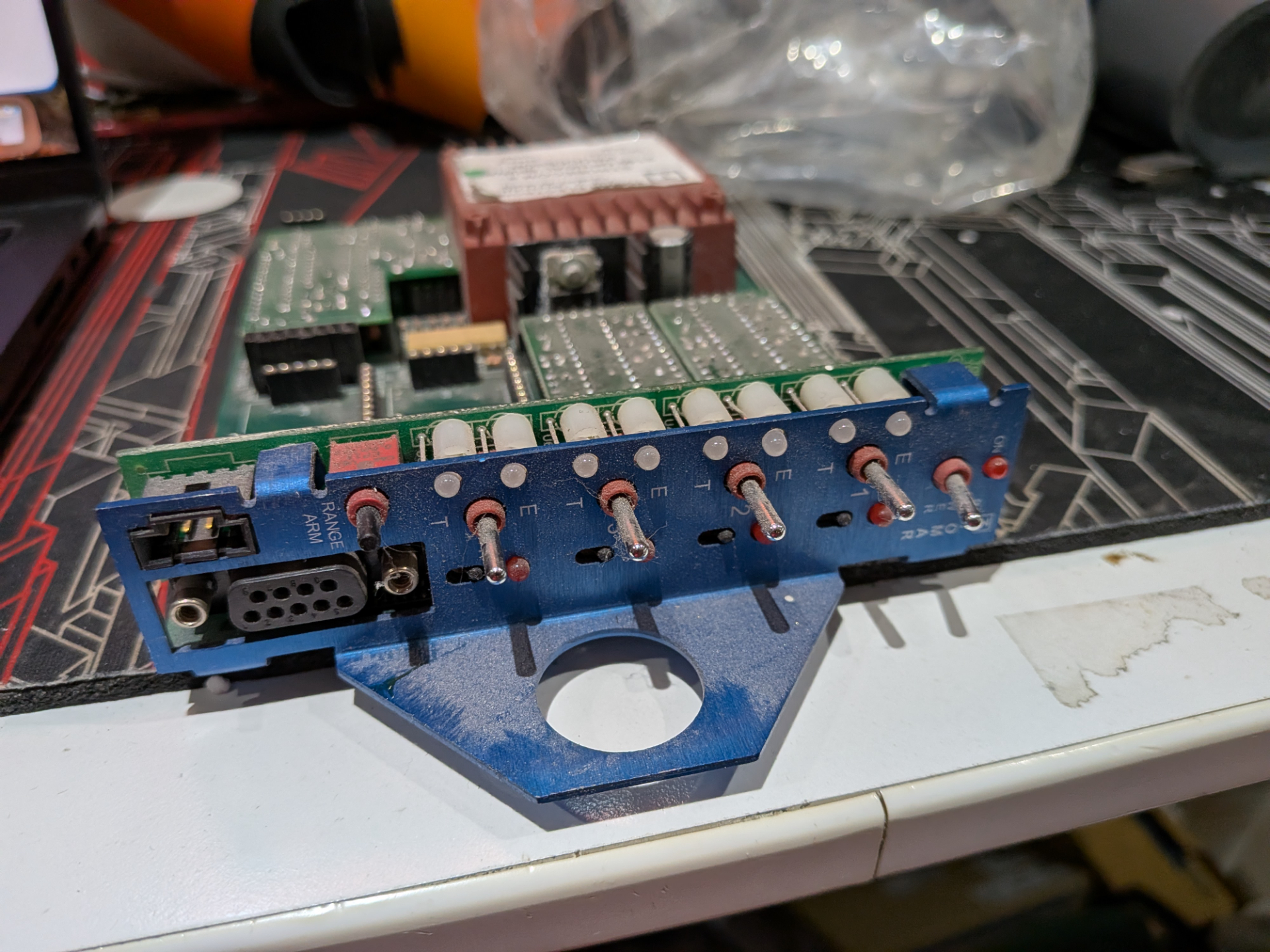
At this stage I have a OSP, with no rack to put it in, no detectors, and no emitters. Usually this is fed from 240v off the traffic controller card slot. I don’t want to deal with mains, so figured out where 5v was being regulated and found some pin headers to supply my own power. The card itself has a PIC for each decoding channel, and then a central controller. They talk over I2C - my card had two channels installed. There’s a RS232 port used for configuring/talking to the central controller. The switches on the front allow testing that the card is functioning correctly - important to note here that these switches do not create test signals on the decoders - it just tells the decoder to send a preempt signal to the main controller.
So simple, we turn it on, use the software to configure the controller to allow everything, then throw some signals at it to see what decodes.
Even traffic light yaks need shaving
It was pretty easy to identify the baud rate (4800 8N1) of the RS232 connection, however the software to talk to the card isn’t available online. You can purchase it from Tomar for $600.00 USD - which is pretty rough that you have to buy along side the hardware - yay capitalism. Even if I did sink money on that, I wasn’t sure if they would actually sell it to me.
Configuring the card was important as I needed to know what codes were configured and have a way for automating logging of successful detection.
This stumped me for the longest time as I couldn’t figure anything out of the output by just guessing its protocol.
That is until I found a really old copy of “OSPsoft 2 User Manual” using the way back machine on the Tomar website.
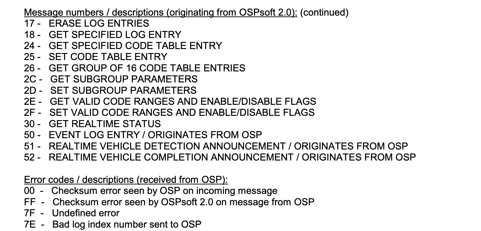
This little section of the manual provided the hex values of the commands and also what the error codes were - along with hints of the data format.
From that I was able to piece together enough information to change ranges, enable uncoded signals and look at logs. The other part was that the user interface in the manual nearly matched the data that was sent in each configuration message. So I was able to work through the screenshots to determine what bytes did what things.
There were a few fun quirks along the way. A lot of the values are hex encoded for some reason, and sometimes ascii encoded. For example getting or setting a sub group requires sending a byte with the ascii encoded number of that group so for group 1 would would send b'1' using Python. However there are 16 sub groups and you can only send a single byte for this parameter. They actually overflow the ASCII conversion so the 10-15 become b':', b';', b'<', b'=', b'>' and b'?'.
With the uncoded ID enabled, I was able to wire up an Arduino Nano and generate a 14.035hz tone and successfully get the unit to show an emergency preemption light on the front panel - along with log some output. Seeing that little light come on was a relief because up until this point I wasn’t sure if the signal processor actually processed the pulses.
Coded messages
The next challenge was coded messages. The first thing I did was run a bunch of tests with the unencoded message to understand what the limits were. It took 33 bits to trigger an unencoded preemption, the min pulse gap length was about 71.010ms, and the longest was around 71.260ms.
From the GTT patents I expected there to be two pulse lengths, a short and long, and based on the spec sheet from Tomar it supports 65000 vehicles - so roughly 16 bits of vehicle ID information.
We still have some questions though:
- Is there a preamble - and if so how long and what does it look like. If not, how does the system know the start of an ID
- Is there a checksum
- Are the vehicle IDs using some sort of gray code or De Bruijn sequence?
I pretty much started with shoving random bit patterns into the system and logging what came out. The intention here so to find something that decodes - even if we don’t know what it means. We vary the pulse delays from the range we found above.
This didn’t get me very far, so I built something a bit more controlled. I programmed a bunch of formats/rules to try - such as repeat the sequence every 15,16,17,18 bits. Use a nominal frequency every 2nd pulse.
My thought process is that if a checksum existed, it would be a max of 16 bits. Eventually we might find a match. I tried a bunch of experiments.
Eventually one of the experiments returned two different successful decodes. The pulse stream was logged. The problem was that playing those back again didn’t result in a decode. I did however find that playing it back it would decode once in maybe 10-20 decodes. Not great but it’s a starting point. The pulse stream was effectively repeated at 17 pulses, the last pulse delay was long.
From here my thought was that one of the bits were being flipped creating a valid preamble. I started flipping bits but this made decoding worse! If there’s no preamble - how does it know the start or finish of the vehicle ID?
The secret third option. The last pulse in the repeating pattern was a long delay. What if I bump just that pulse out by even longer. Success, reliable decodes.
I ran through some ranges of pulse delay timings and figured out reliable timings (note that were are using delay/delayMicroseconds in Arduino, so aren’t exact figures. I don’t have a great way of measuring exact pulse delay times)
l 71215  +/- 10 (safe)
s 71090  +/- 10 (safe)
p 71260 +/- 10 (safe)
[p,   s,s,s,l, s,s,s,s, l,l,s,l, l,s,s,s] (repeat at least twice)
Decodes as 61,223 (0xEF27)
The vehicle ID isn’t encoded in any special way, the key part is having an extra slightly longer delay for the first/last pulse and repeat at least twice (to get up to 33 pulses - both sequences must match).
Transmitting
As a PoC I built my own little detector. It’s not using the amplifier circuit, is missing all the filtering and is generally just terrible because I don’t know what I’m doing - but it works well enough to test.
In the video I demonstrate IR signal triggering the signal processor for a coded Strobecom II signal.
I also built using a Raspberry Pi Pico (important, the PCB must be pink) and connected an IR LED to it via a resistor.
#define l 71225 - 0xffff
#define s 71100 - 0xffff
#define p 71270 - 0xffff
#define LENGTH 17
#define on 200

unsigned int payload[LENGTH] = {p,    s,s,s,l, s,s,s,s,  l,l,s,l, l,s,s,s };
int pos=0;

void setup() {
  pinMode(0, OUTPUT);
  digitalWrite(0, LOW);
}

void loop() {
  delayMicroseconds(0xffff-on);
  delayMicroseconds(payload[pos]);
  digitalWrite(0, HIGH);
  delayMicroseconds(on);
  digitalWrite(0, LOW);
  pos++;
  if (pos >= LENGTH){
    pos = 0;
  }
}
I adjusted the timing a little bit for the Pico but now get reliable decodes with the above code by pointing the IR blaster at my make shift detector.
But I still need to find the vehicle ID to “hack” the system right?
Yes. Kind of. Maybe
Some of the Tomar controllers don’t actually permit configuration. So as long as you configure an ID within the default range you are done.
Systems that do allow configuring - might be left with the default configuration. As above, if this is the case, you are done.
For systems that are configured, we should look at how that works. First quirk is that the controllers I’ve looked at require setting a ID range. This is a max of 1000 sequential vehicle IDs. This is due to the limited amount of memory on the controllers. So while it can decode 65,000 vehicle IDs you must set a range, such as 4000 to 5000, that your system will use. Inside that range you can enable/disable different IDs. By default they will all be enabled. I suspect in most cases this is most the configuration done.
In the case that the controllers have disabled all vehicle IDs by default, then you can expect maybe 50-100 vehicle IDs to be enabled in a typical system. Given that it takes 2.5 seconds to send a signal, binary searching this space isn’t all that time consuming when its 100/65000 codes.
The worst case is that the system is programmed with a single ID. That would take 45 hours. On the flip side, if the system is coded with a single ID, it’s really hard for them to change that ID as multiple vehicles will need to be reprogrammed.
What can be done?
Both Tomar and GTT know that these systems are insecure. Both have various patents (sigh) of alternative authentication schemes, such as using a combination of IR and radio. I imagine most traffic agencies are moving away from this optical based approach anyway. Every state/area has different approaches to EVP.
So can the Flipper Zero be used to change the traffic lights?
Probably. The thing is though, I don’t own one and I don’t have a Strobecom detector.
The timing on the Tomar system is tight, flashing roughly 14hz isn’t good enough. If your LEDs don’t have a quick rise time, then they’ll get filtered out and if the system requires codes you need an active code. There’s also nothing stopping you from adding a xenon flasher (apart from the risk of high voltage electronics) to a Flipper Zero.
I’m pretty certain that it’s possible to get a Flipper Zero to trigger Strobecom II preemption - I just don’t think anyone has done it yet. Opticom on the other hand, probably has happened.
Further research
My OSP only lets me configure up to the advertised 65,000 IDs. That means there are 536 IDs that are unconfigurable. After this post goes up I’m going to try to send some of these IDs to see if they trigger anything fun.
I’ve placed my notes, Pi Pico code and OSP reverse engineering in this GitHub repo.