The clicky 4LO transfer case : bullshit LandCruiser 200 troubleshooting and repair
Jul 30, 2025
If you’re reading this looking for possible solutions to Toyota LandCruiser 200 series 4WD system or door locks - remember that this post is very bias’d towards a very specific problem. If you have a sun roof then check electrical connectors and wiring for corrosion and water damage first. If your actuator isn’t working correctly start by cleaning it.
It’s unlikely that your issue will be the same as ours.
While/after visiting Adelaide for Horus 64B launch our car had developed two issues. The 4HI/4LO actuator was failing to operate correctly - the main symptom was clicking/ticking.
The second was slow door locking action. Lets tackle this one first. For Horus 64B launch I decided to locate the door motor wire for a passenger door and disconnected it. The reason for this is that it allowed us to safely run cables out the window without the risk of coax cables being pulled out from accidental door opening.
After the launch I wired the door back in but the doors unlocked really slowly and often the passenger door I modified failed to operate at all. I checked all the fuses, voltages, terminals and everything seemed fine. Disconnecting the motor and the other doors look worked ok, though maybe a little slower than I was used to. Maybe it was a coincidence? I’ve ordered a replacement door motor to see if that resolves the issue. We’ll return to this some other time.
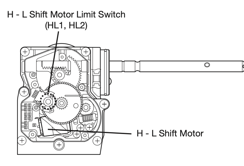
Back to the 4LO problem. The issue was first discovered when performing a routine exercise of the actuator. This happens so that the unit’s grease doesn’t dry up and cause issues with the motor and contacts. Unfortunately the operation failed and not in a great position either. It was neither in 4LO or 4HI, and we were still in Adelaide. The way these work is a long rod that has a rack and pinion that pushes a shaft in and out to engage high range or low range. My initial thought was open up electric motor assembly, either fix it or at worst push the rack into the correct position to get home.
This is from a different vehicle but it shows the core components of the actuator
The assembly is in a plastic housing. I foolishly thought what I was removing was just a plastic cover, however both sides hold components. So in removing the plastic cover, which required a bit of force to break the seal, many of the components fell on the ground.
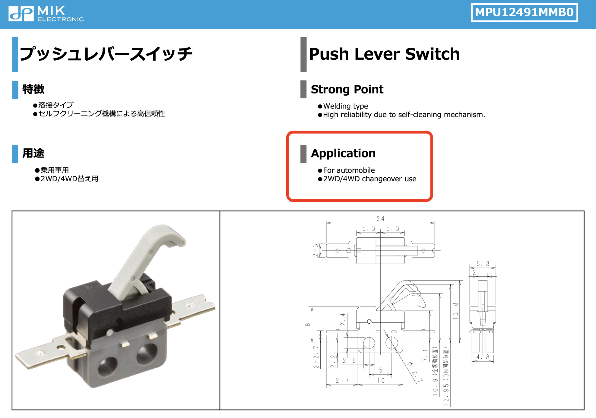
I’m not sure if I caused the microswitch to be damaged (I assume so) or if its been broken the entire time - but that seemed like a problem. Seems simple - just order a replacement micro switch - however that microswitch is unobtainable. It seemed to have only been made specifically for these transfer case actuators.
I forced the rack into the correct position and we drove home without issue.
With no way to obtain a replacement micro switch (did consider 3d printing) and being unsure of the exact issue Droppy ordered a replacement actuator - $700. The actuators are known to get weak or not work correctly after time. This is a 2008 vehicle after all.
The “correct” way to perform this replacement is to drop the transmission and replace the entire actuator assembly (both center diff and 4lo). That’s not something we are going to do. The reason for this is that the actuators are “clocked” or aligned in factory so that the encoder slip ring contacts are lined up with the position of the rod. Removing the main gear removes this alignment which means it requires realigning/clocking/timing. IH8MUD (huge shout out, always a ton of good info there) has some advice on doing this alignment - but I’ll share a trivial method below.
When the new actuator arrived we instantly noticed that the microswitch for the 4LO system was missing. This actually wasn’t to unexpected - we were aware that new revisions of the part were missing the switch. The diff lock side still had the switch if we needed it.
The first step was to install the new 4LO actuator as is and see how it goes. The clicking remained and worse is that it didn’t put the rod into the correct position. It took about 6 to 3 minutes to change - and the slow transition resulted into some not nice noises (while it was getting in or out of gear). We initially thought that given that a DC motor was used that there was some calibration process that configured a motor powered timer. This was not the case.
Side note here. I was wondering why there’s “bad noises” when placing the car into park when the car is in between 4LO and 4HI. I think the reason here is because the output from the auto transmission has no resistance and is freely spinning as the wheels typically would force the shaft to stop. Putting the car into park will be resulting the parking pin trying to be inserted with the output shaft moving. If you know your not in 4LO or 4HI (neutral) then stop the car in neutral gear then shift to park.
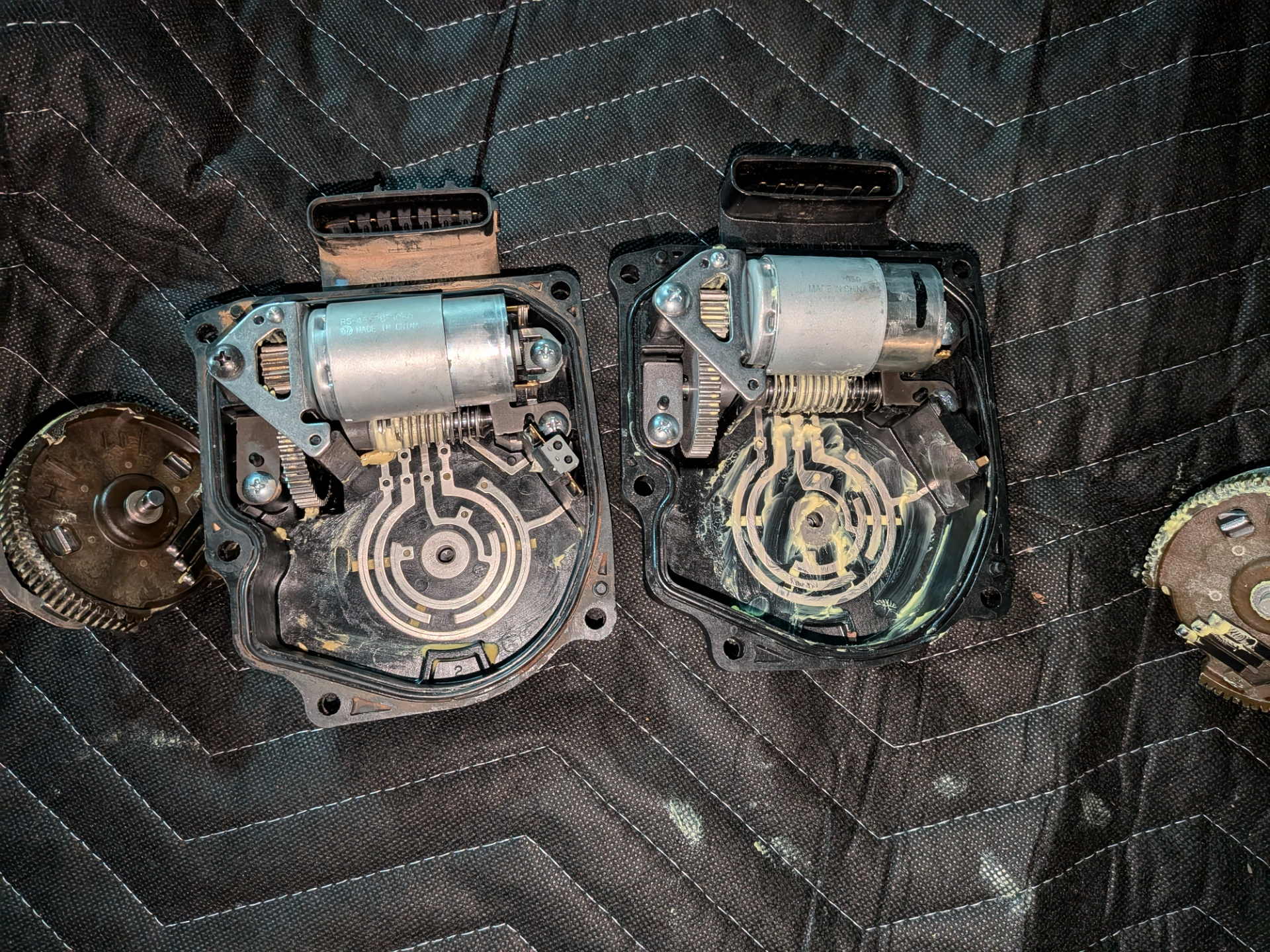
When looking at the new and old part more carefully you can see why. The positions of the contacts are entirely in a different spots.
Droppy went and found a bunch of the part numbers and it seems like there are wide variety of parts with unknown compatibility between series.
Actuator
36410-60101 is 2017-11 -> 2010-01, but 36410-60102 can be substituted for that according to the parts list.
36410-60102 was fitted 2010-01 -> 2010-09.
36410-60120 (which we have) was fitted 2010-09 -> 2015-08

4wd computer:
89533-60240 (2007-09 -> 2007-11)
89533-60241 (2007-11 -> 2010-09)
89533-60380 (substitute for above) (2007-11 -> 2010-09)
89533-60242 (2010-09 -> 2012-01)
89533-60390 (substitute for above) (2010-09 -> 2012-01)

Transfer case:
36100-60B11 (2007-09 -> 2010-09)
36100-60B12 (2007-09 -> 2010-09)
36100-60B20 (2010-09 -> 2012-01)
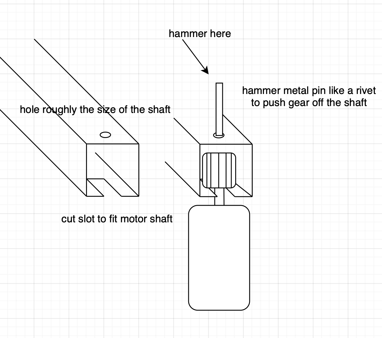
So the next idea - use the parts from the new actuator but the base of the old to rebuild one good one. Motor, gear, microswitch all replaced out. A gear puller was fashioned out of some box section (this was so I could use the center diff lock motor).
With the new/old one built it was reinstalled in the car and….. the same issue. Even running the assembly without the rack it still struggled to move around.
At this point all the wiring to the actuator was tested. All good and fine.
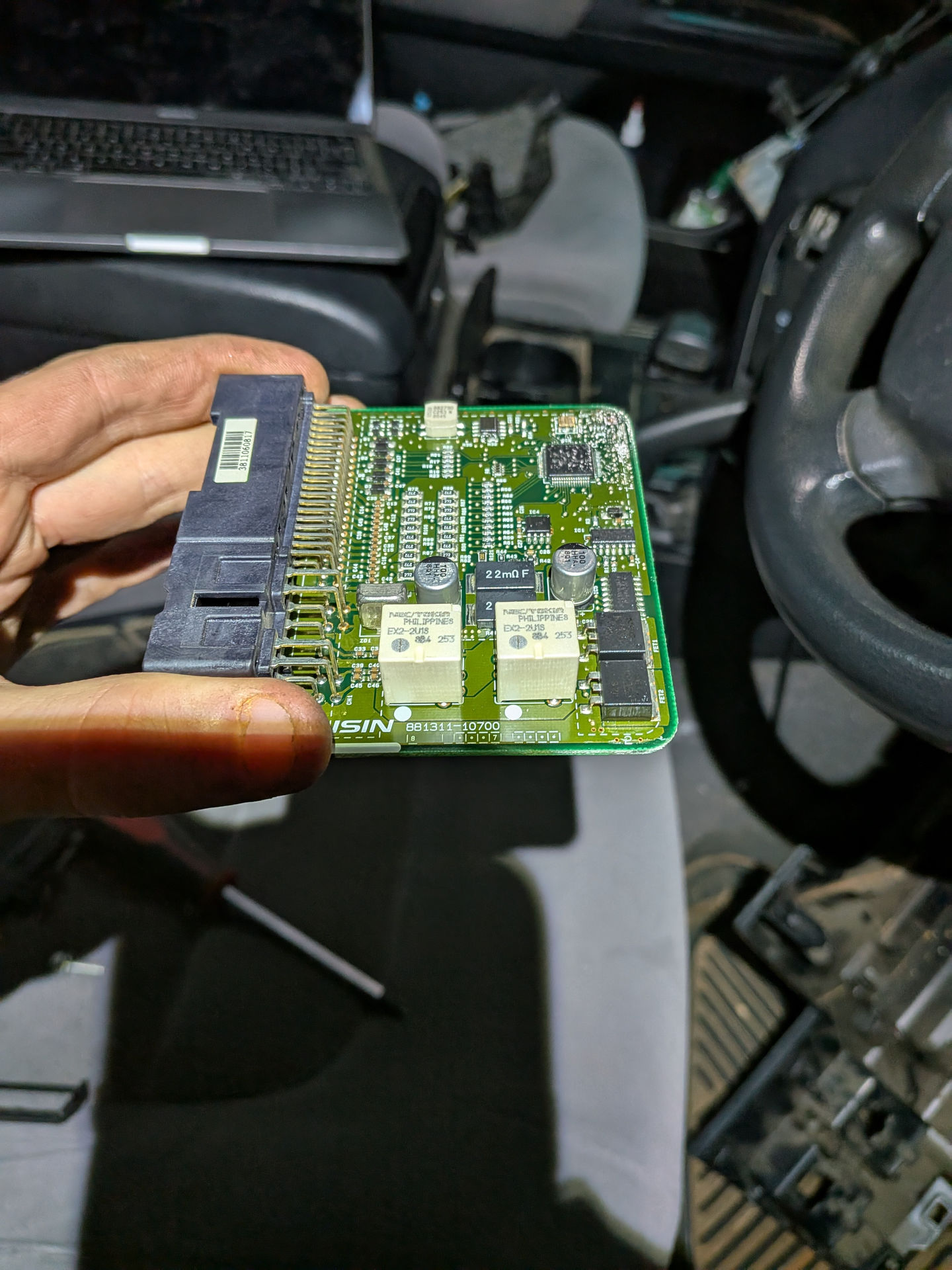
I guess the 4WD ECU is dead? Alex helped me remove the drivers side dash and panels to get to the 4WD ECU.
Removing the case from the 4WD ECU, nothing revealed itself.
Although the 4WD ECU has CANBUS maybe it’ll still set the actuator position at start. After running through the wiring for the actuator and 4WD ECU a ton of times we were able to trigger it to run the actuator on the test bench and …. it works. So what the heck is going on in the car.
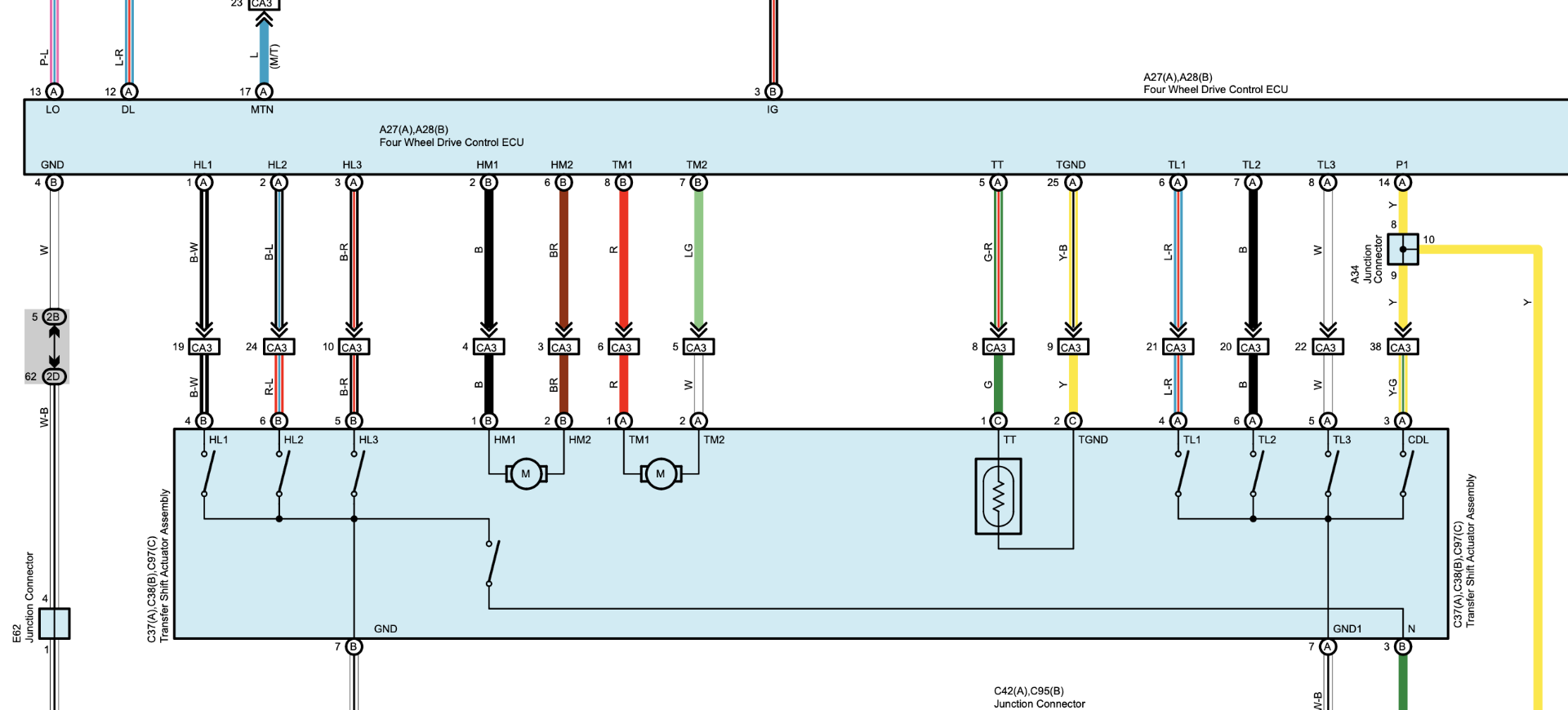
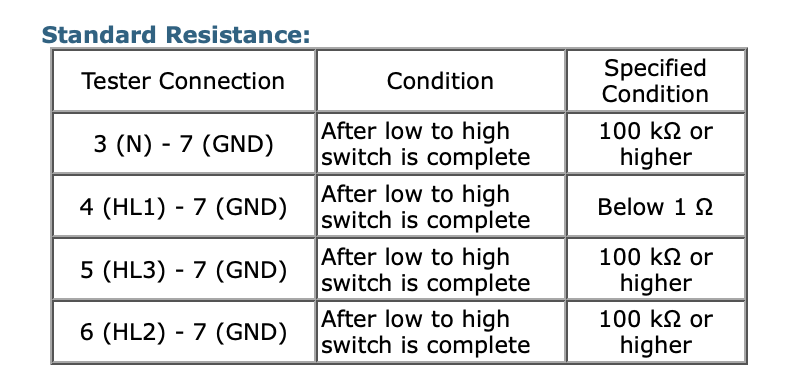
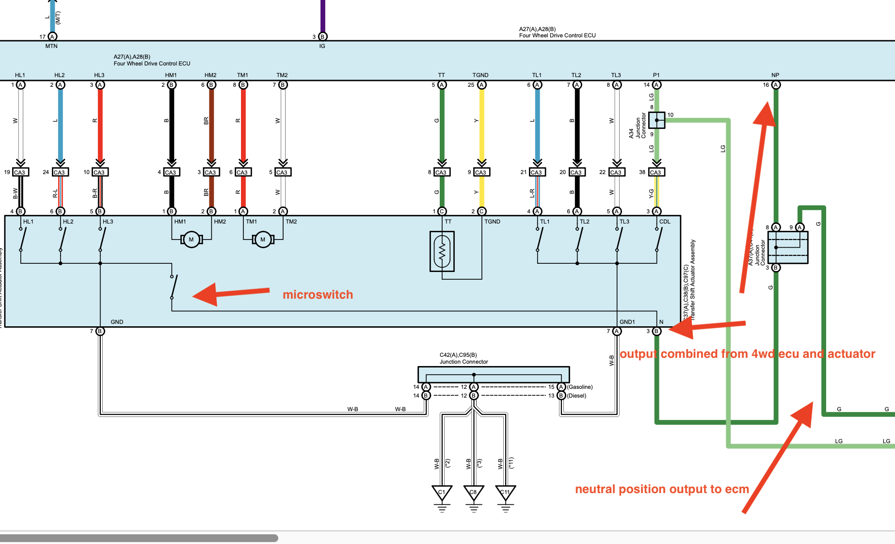
The 4WD ECU can (well ours can) be tested on the bench by faking some signals. We can use the service docs to find those signals.
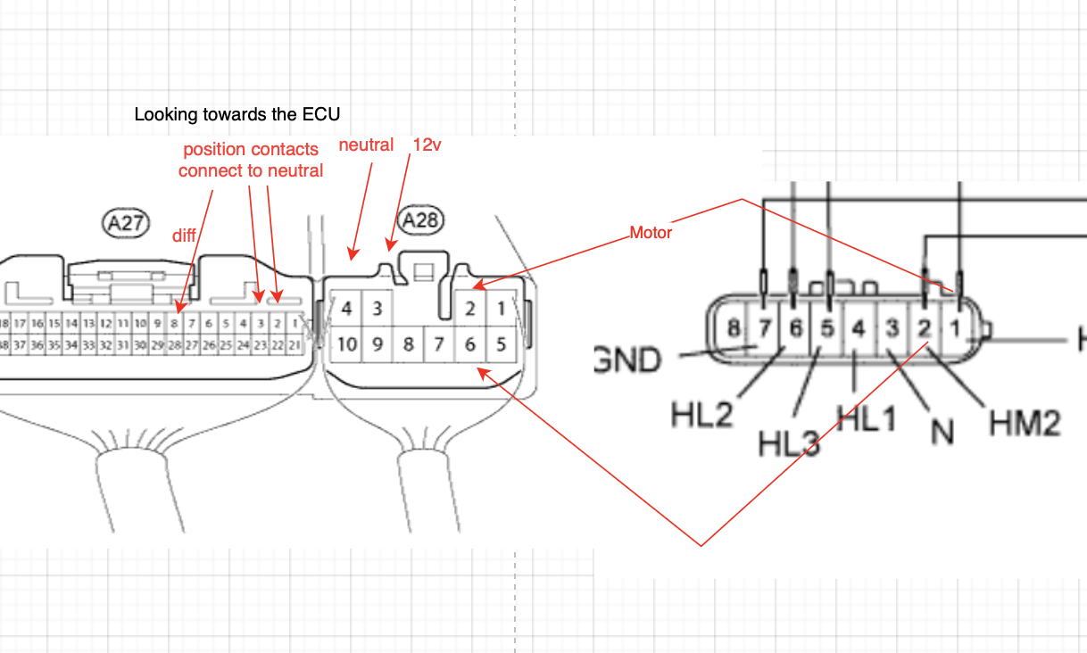
The motor is connected to pins 2 and 6 on the large pins of the ECU. These correspond to pins 1 and 2 on the actuator side. You can connect these either way during testing if you aren’t placing the gear assembly in the housing as the motor will just spin the opposite way.
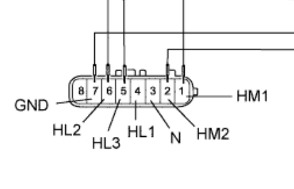
Pins 1,2,3 on the small pins correspond to the position sensing of the 4HI/4LO actuator. These are either disconnected or connected to neutral to signal position. From memory I connected pins 2 and 3 to neutral to trigger the motor to spin. This should signal to the ECU that the transfer case is in between 4LO and 4HI
For power of the ECU, pin 4 on the big contacts is neutral and pin 3 for power.
I also connected pin 8 on the small contacts to ground to simulate the diff being in the correct position.
To make the connections I used alligator clips on the large pins alternating between using the pins or making connections on the back of the connector. For the small pins DuPont connectors were used.
Please don’t trust me, double check my work.
Thinking some fucky electrical thing was happening we disconnected all the dual battery system, removed all the electronics that were plugged in and removed all the main body fuses that weren’t necessary. This did not help.
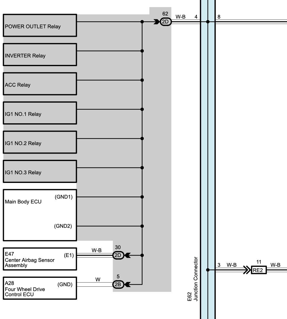
The next part was to test the wiring to the 4WD ECU itself. We noticed a ~5 Ohm resistance between the 4WD ECU neutral terminal and the body of the car - which seemed a little high. This indicates a wiring harness fault. Uh that’s not fun.
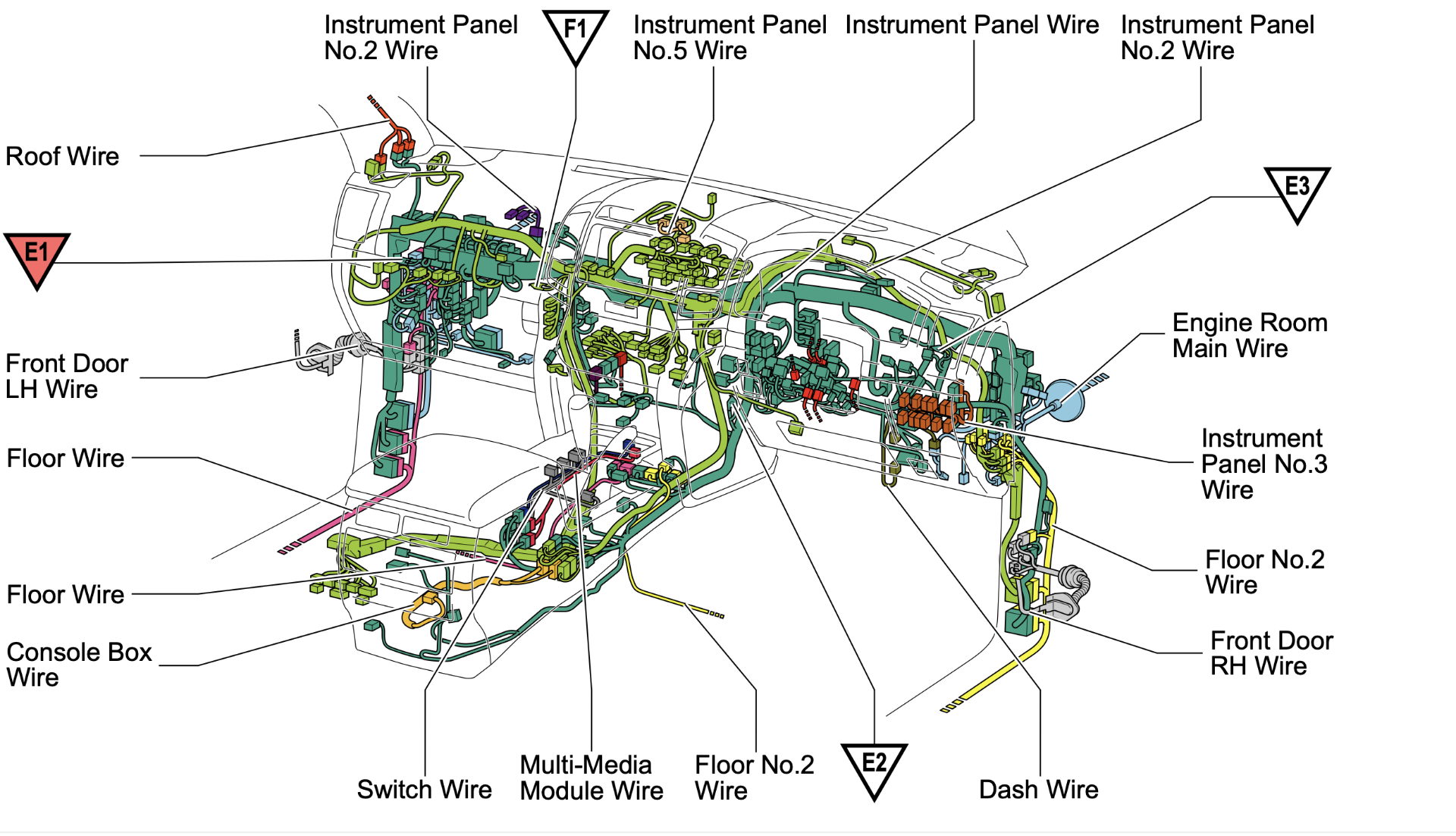
I expected that the neutral would be found near the drivers dash as well - however the neutral runs all the way back to the Main Body ECU in the passenger side dash. Sigh. Ok all the passenger dash ripped out to get to the Main Body ECU.
I spent far too long trying to work out how to remove the Main Body ECU however once the glove box is removed it does just come straight forward. We had a lot of extra cables in the way that made that non obvious.
With the ECU removed we tested the resistance between the two ends of the wiring harness - fine. We tested the neutral between the Main Body ECU and body earth - fine. What the heck is happening. Then I decided to test the neutral across the front and back of the ECU. 350 Ohms.
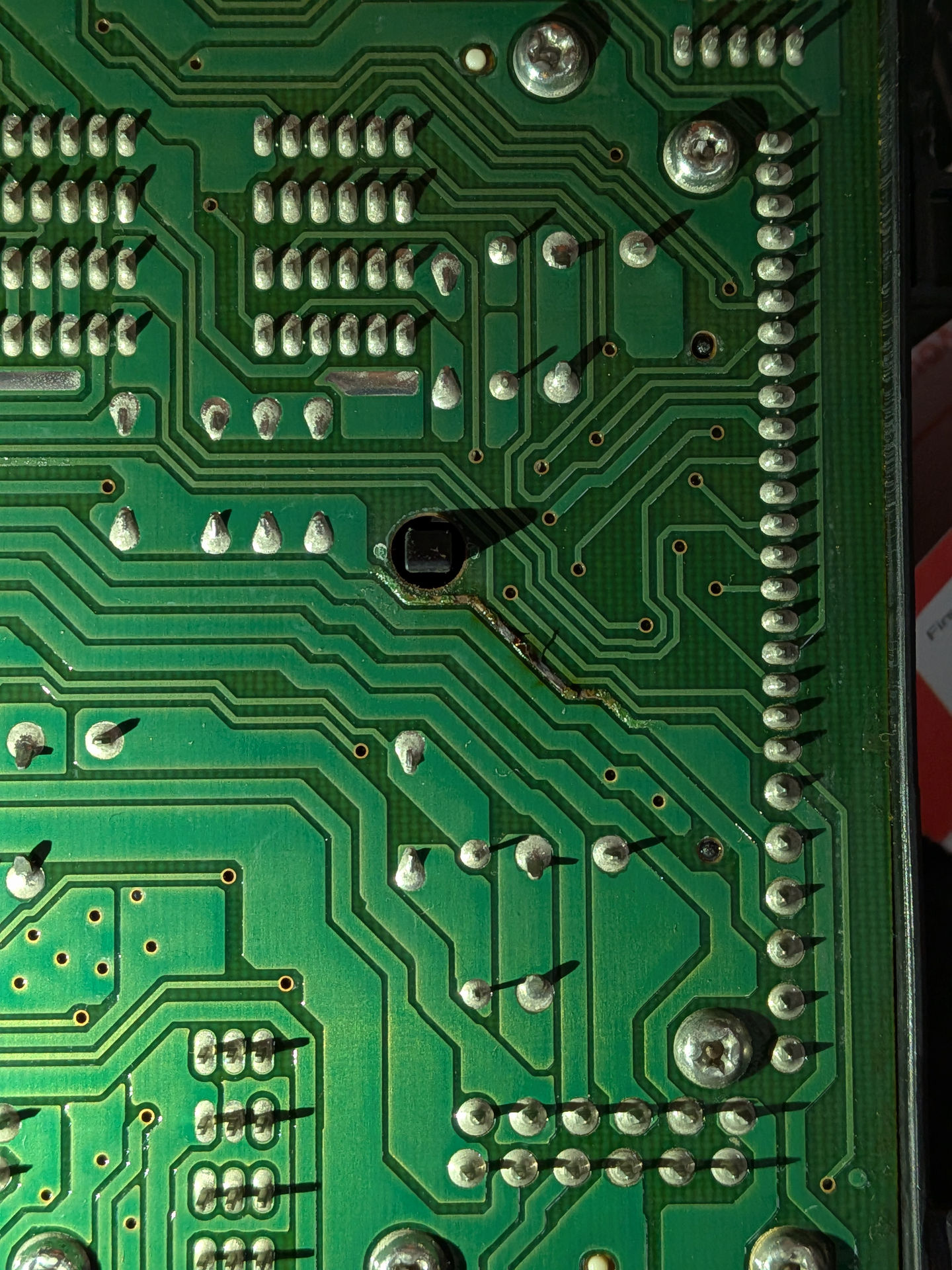
That’s uh. weird. We removed the cover from the ECU and found the secret “fuse”. For some bizarre reason Toyota thought it was completely ok to run the neutral for bunch of subsystems across this tiny trace which wouldn’t be able to handle the max fault current in the slightest.
At least the fault was self evident though a clean break would have made troubleshooting easier. Some bodge wire was added. The actuator motor now spins fine.
So how did this happen. Well remember at the start when I said I was messing around with doors. I believe while I was metering out what to cut I caused a short. I didn’t think much of it at the time because no fuses blew and everything worked ok. Now that that the Main Body ECU PCB trace is fixed the doors work fine.
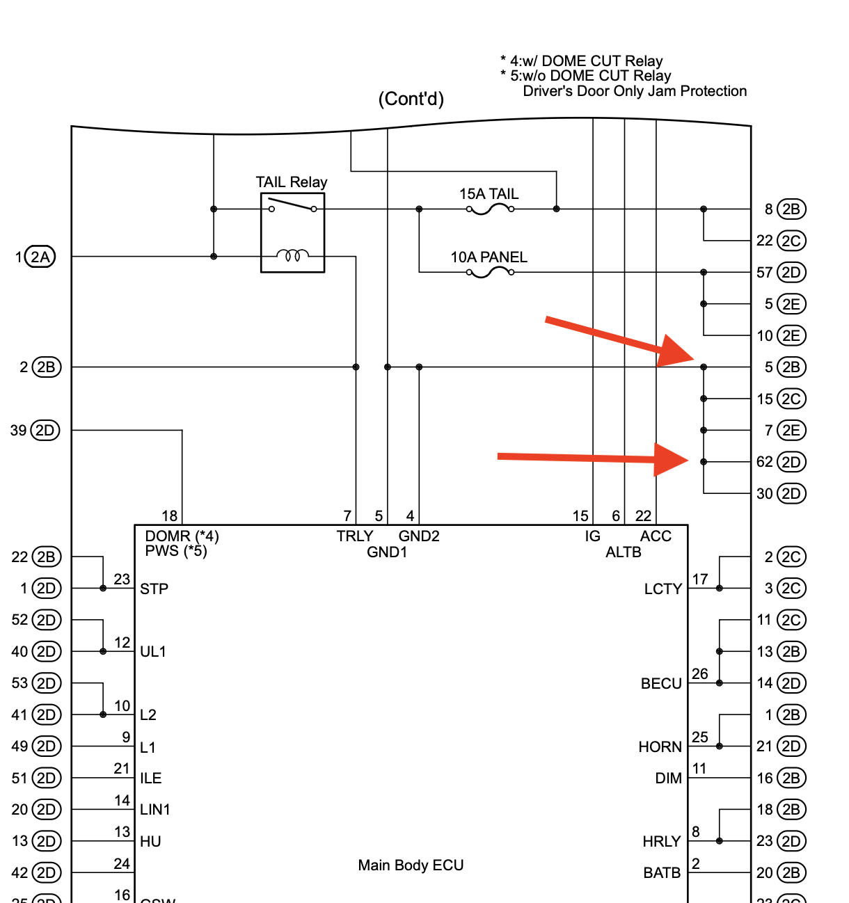
I did wonder if maybe there was a lifted neutral as well. But checking the circuit diagram reveals that everything I’ve discovered is the correct/only neutral path.
What was left to do was align the actuator position/timing (“clocking”). I discovered a fairly novel way of doing this. Hold the assembly in your hand, connect it to the car, but don’t connect it mechanically. Hold it in a way that your hands are clear from the gears (it moves faster than I thought it would), but applying a bit of force to the shaft to keep the contacts down - then have someone turn the car to on (don’t need to crank) and let the motor spin and it should stop at the correct position. For us, setting the 4WD to 4HI is easiest as the then rack just needs to be pushed ALL the way in. Without adjusting the position of the actuator gear, now insert it into the rack and screw it down. It should be in the correct position.
Now about that micro switch - it’s not required. I suspect the purpose of this switch was to signal to the car/transmission that the car was effectively in neutral. I believe it might throw an A/T/P warning (warning you that the transmission isn’t in park so the car can roll away if the parking brake isn’t engaged) when this switch is active. I guess maybe Toyota were concerned that the 4WD ECU might fail and not report the neutral position, or possibly that part might be replaced with one that doesn’t output the signal?
However the transfer case already knows this information (it’s how it knows to keep driving the motor) so they likely just removed this from future versions since the switch was pretty useless and kept breaking. I tested that the switch isn’t needed by taking the left over no micro switch version and letting it run from 4HI to 4LO without issue.
Here’s a video of the actuator being clocked and the microswitch not being required.