Caution. Using traffic preemption devices such as described in this blog post could impact emergency response times. The use of these devices outside their approved use may be illegal in your area. Traffic light preemption systems are typically logged and intersections often have video recordings. Traffic lights might not respond how you expect. All information in this blog was derived from reading manuals and testing in a lab.
Additionally - I’m not an expert in this field. I don’t maintain emergency vehicles, traffic controls systems or have any formal training. This is just me vomiting up information I read.
Say you are an paramedic and the patient in the back of your ambulance is leaking all the human goo required to keep them alive. Alternatively you can be Karen in the family SUV taking your 2 kids to band practice 600m away from home. Between you and success are 18 thousand traffic lights and 2 million vehicles because of car centric design. It would be great if in emergencies (like being late to band practice) you could magically control the traffic lights to give yourself all greens.
This is what traffic preemption is. For emergency vehicles this is usually called Emergency Vehicle Preemption or EVP. There is also Transit Signal Priority, TSP, which is used for mass transit such as buses and trams.
There’s many different systems for EVP and TSP. We’ll be looking at just a single type in this post, but first I want to explain some of the hidden complexities in these systems. Obviously we want to turn the light green when there’s an emergency but whats involved with that.
First the driver of the vehicle needs to declare an emergency - we don’t want every off duty emergency vehicle stopping traffic lights
Then the traffic lights need to know there’s an emergency.
Specifically, the set of traffic lights that the vehicle is driving to - we don’t want every set of traffic lights to change in the city
The traffic lights themselves also need to know where the vehicle is coming from. We want all greens, not all reds
Before the days of super reliable vehicle positioning solutions, this was a bit of tricky problem to solve. Additionally, not all traffic lights are wired up to a central location. Some solutions involved directional antennas. Some systems tried to identify strobing lights. While there have been several solutions to this problem, the one that really won out in the 90s and 2000s was infrared. It might be a bit of a surprise to think that the principals behind a TV remote ended up as critical infrastructure.
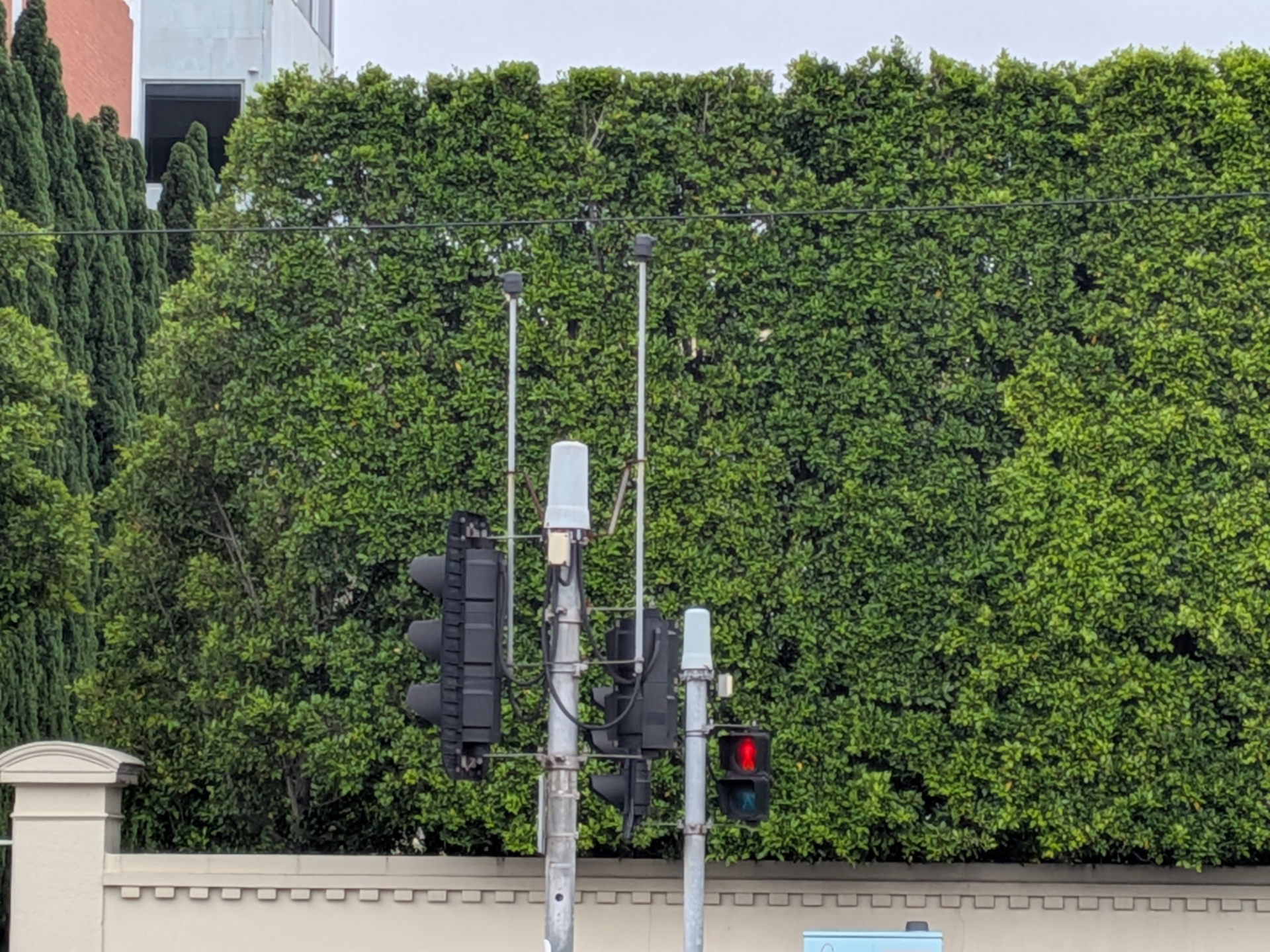
Infrared works really well in this use case as an emergency vehicle can flip a switch (maybe its just wired to the same one as sirens). The emitter can be placed on the roof of the vehicle and pointed in the forwards direction. At the traffic lights several detectors can be placed facing various directions of traffic flow. An optical signal processor will receive the data from the detectors and determine which cycle the traffic lights should switch to.
The Strobecom Detectors are at the top of the traffic stack on the big long sticks
Ah, so the Flipper Zero can control traffic lights?
At this point in our story. Maybe. There are several videos on YouTube, forums and social media sites claiming this. The thing is, it’s very very very easy to fake a video like this. Wait for the traffic light cycle to just about start - hit the button, look amazed. At the same time, it does actually work…. for some traffic lights.
Some systems have confirmation lights to let emergency services know that the signal worked - though I haven’t seen many of these in practice. A good way to confirm if these videos are real is checking for these confirmation lights.
The early implementations of this infrared detection system used IR pulses at 14.035 hz. The Flipper Zero can likely replicate this just fine. For transit priority this is usually lower, like 10hz, 9.something or 6hz.
Obviously having people mess with traffic lights using an IR LED and a 555 timer is not a good thing™. So both GTT (3M at the time) Opticom systems and Tomar Strobecom implemented different ways of encoding data into the signal. Not only did this allow for security, but allowed extra functionality like deciding which vehicles get priority over others and opening gates. Of course these two systems are patented and each company even has patents on how they could interoperability, ffs. GTT and Tomar also got into a patent tiff with the two settling out of court. I love when emergency/critical infrastructure is locked behind patents and trade secrets.
We’ll be talking about the Tomar Strobecom system, however the briefly before that, lets take a quick look at the GTT (3M) Opticom system. Through eBay (which doesn’t actually permit selling these devices) I was able to obtain a “Tomar 970APRE-PS-T792” power supply. This might be confusing you as I said GTT system, along with this is the power supply, not the emitter.
Tomar uses Xenon flash tubes to generate the IR signal. The emitters in the Tomar system are actually just the tubes. The logic/smarts happens in the power supply. Tomar sells a range of devices which are compatible with the GTT system and this power supply is one of them.
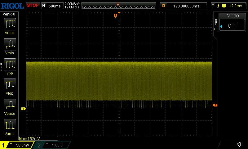
I hooked this unit up to my scope (noting that since we are dealing with possibly kilovolts here we need to be careful…) and recorded a capture.
Note that the scope is loosely coupled to the signal here, basically picking up the noise from the pulses, which is why the capture is a bit weird, but its suitable enough to see the encoding method
In the GTT system you can see that the data is encoded by skipping bits. Something that the Flipper Zero could do if you recorded one of the signals of a configured vehicle ID.
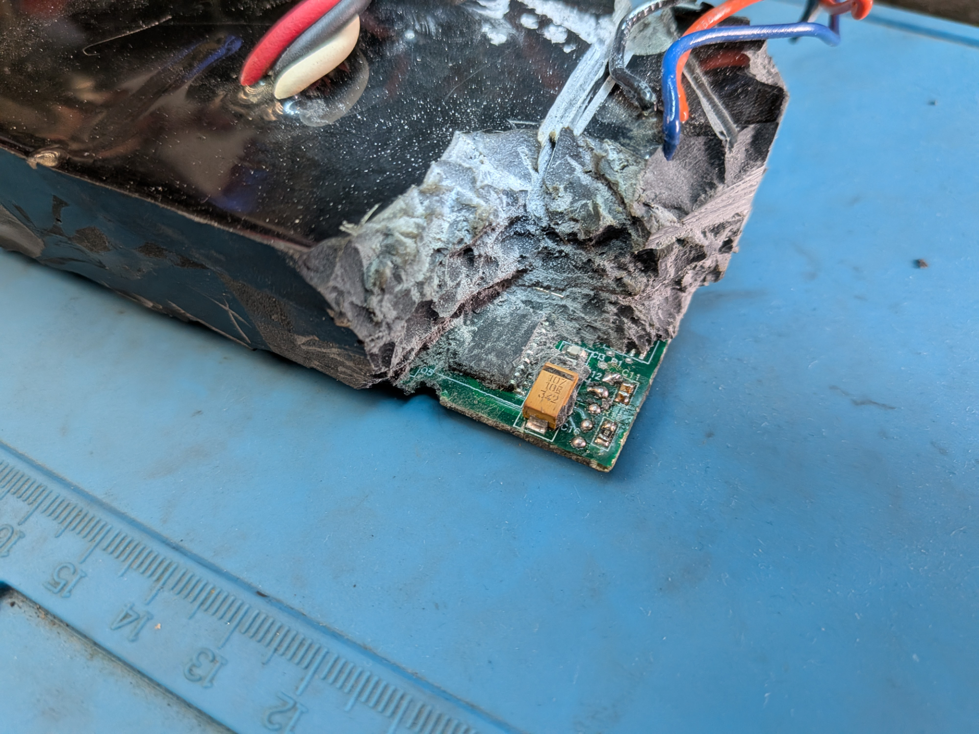
I also went through the joy of de-potting this power supply. Unsurprisingly its a PIC16F628. I believe I can change the ID of this unit, however I haven’t figured out how yet. I believe it’s via J1708/J1587 - it’s also possible I killed it during de-potting…
Why do I care about the Tomar Strobecom II system so much anyway?
Well mostly because I wondered what the little Strobecom II detectors were on traffic lights. I came across VicRoads TCS 055-1-2005.
2.2 SYSTEM SECURITY
The EVP system shall be a secure system that prevents false activations,
unauthorised activations and ‘hacking’.
Games on.
The other reason is many government tender and policy docs specify things like:
be a Tomar® 2140 Optical Signal Processor or similar, fully compatible, processor
Without knowing how these systems work, it’s impossible to building a competing product that would meet the tender requirements, even ignoring patents issues. And I think thats a problem when we are talking about critical life saving infrastructure. Lower cost can mean more installs.
Quick note around Victoria’s EVP system: The TCS 055 copy I have is dated 2005. When observing vehicles today, I see very few with EVP emitters installed and I haven’t managed to capture a real world sample of the signal they emit. My suspicion here is that the Strobecom system is no longer maintained and that GPS / radio based system is used instead. This is just speculation however.
So what do we know about the Tomar Strobecom II system?
We know:
it’s not the GTT system - so likely isn’t using missing pulses to encode data
the emitters are Xenon tubes not LEDs - so bursts of data is unlikely - additionally the Tomar system is specifically designed to require a max of 10 microsecond rise time for the pulses (according to datasheets)
the emitters will likely still be detected by legacy 14.035hz systems
This a bit rough to work with, but we can get some extra clues from patents.
US5519389A “Signal synchronized digital frequency discriminator” is Tomar’s key patent for Strobecom - effectively showing that Tomar can check the timing of pulses
US7417560B2 (and a few others) “Multimode traffic priority/preemption intersection arrangement” from 3M mentions how the Strobecom II system uses variable length delays between pulses to encode data. Annoyingly it doesn’t mention how long, or the format - but its a hint.
Recording pulses
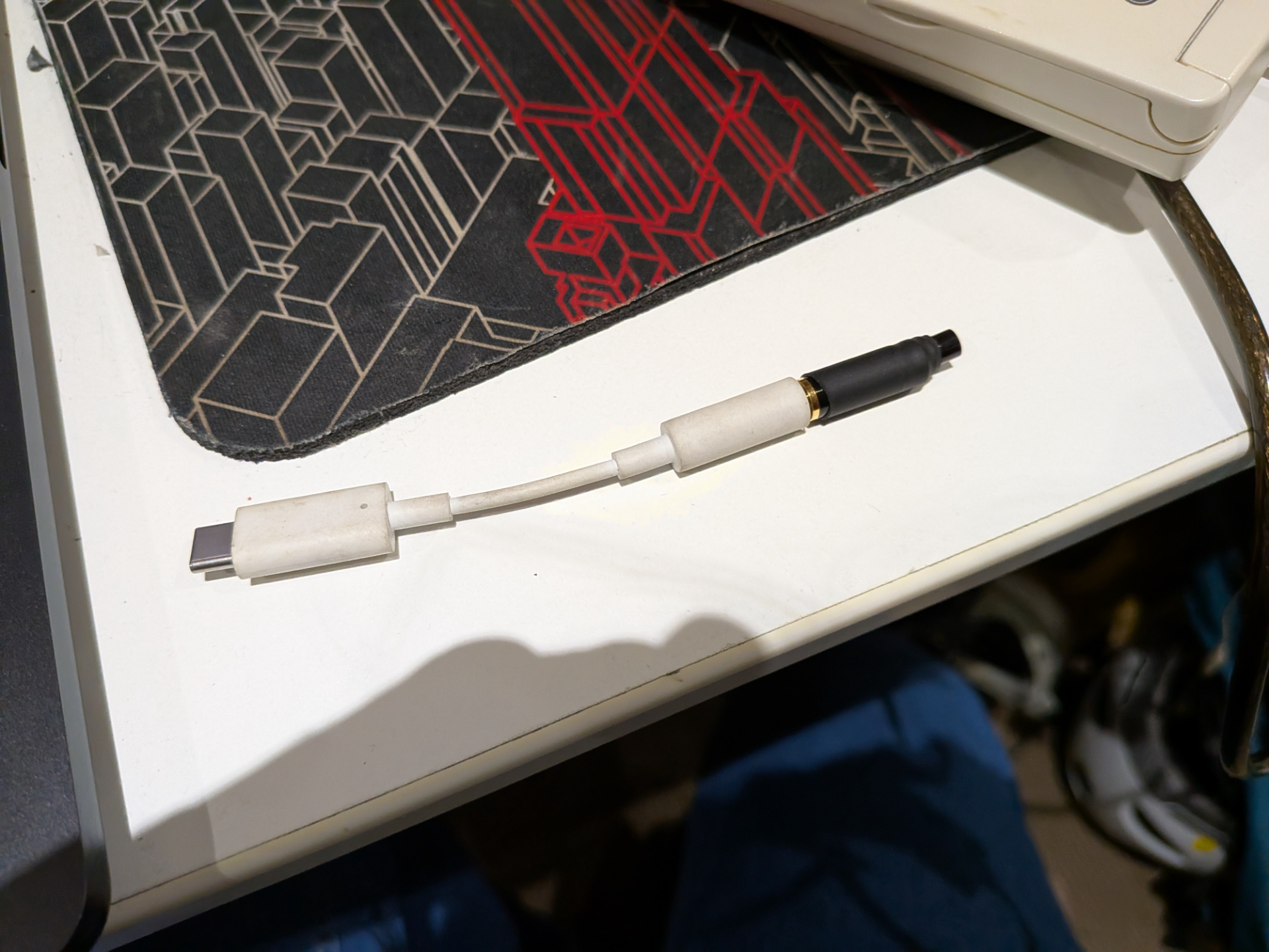
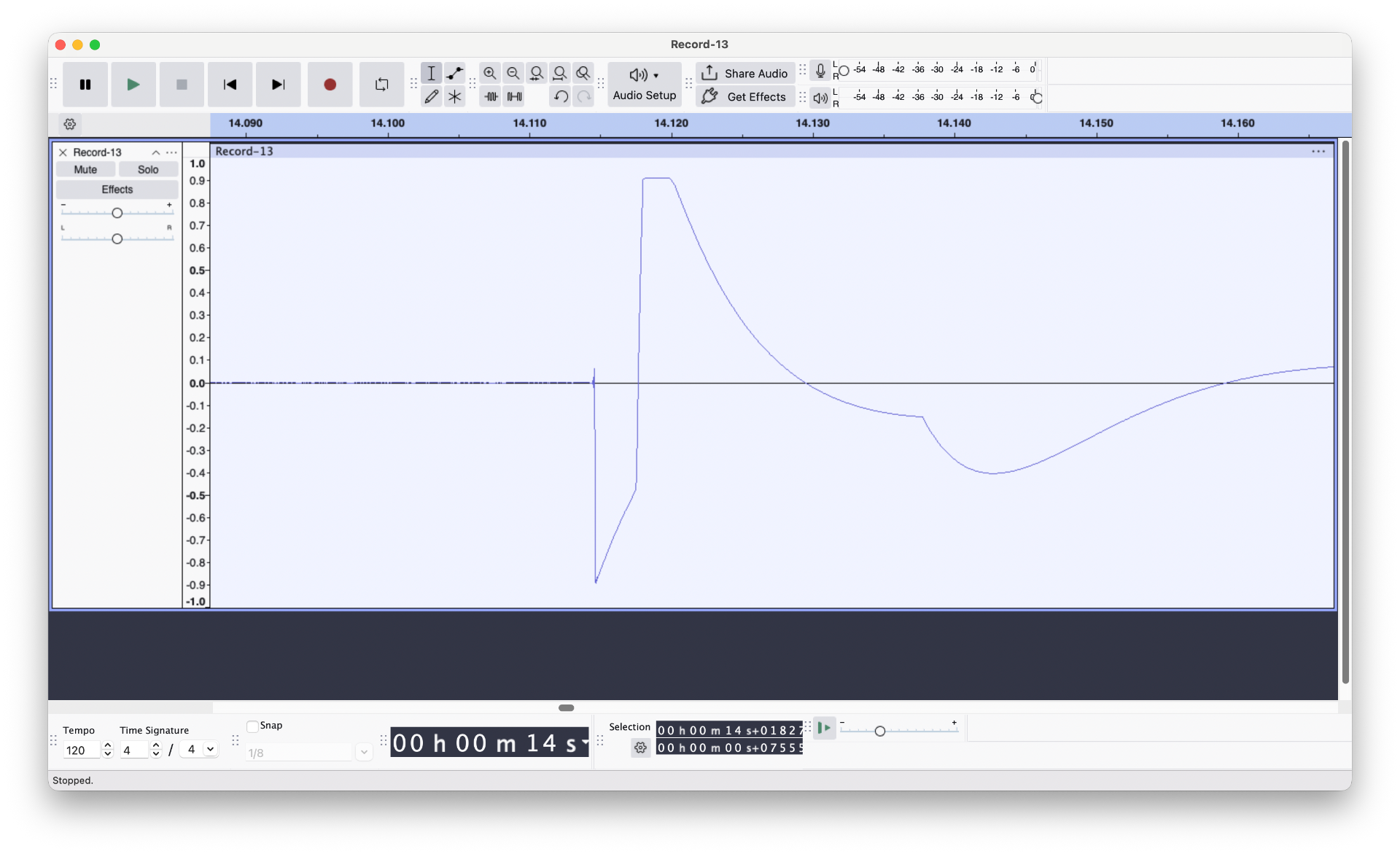
My next thought was, why don’t we just record some. I built this little detector using a Pixel headphone/microphone adapter, wired an IR photodiode in series with a resistor across the microphone and ground pin.
I then tested with a camera flash - and sure enough it recorded the pulse. I was probably a bit too close to the photodiode and the signal went straight into clipping. But that’s ok.
As mentioned above however, the Strobecom system is less widely used in Victoria than I first thought, so even though I have recorded several passings of lights/sirens vehicles, none of them appeared to have Strobecom running/installed. (Annoyingly I’m pretty certain there was one emitting just before I built this device).
Sit at traffic lights and try all the combinations
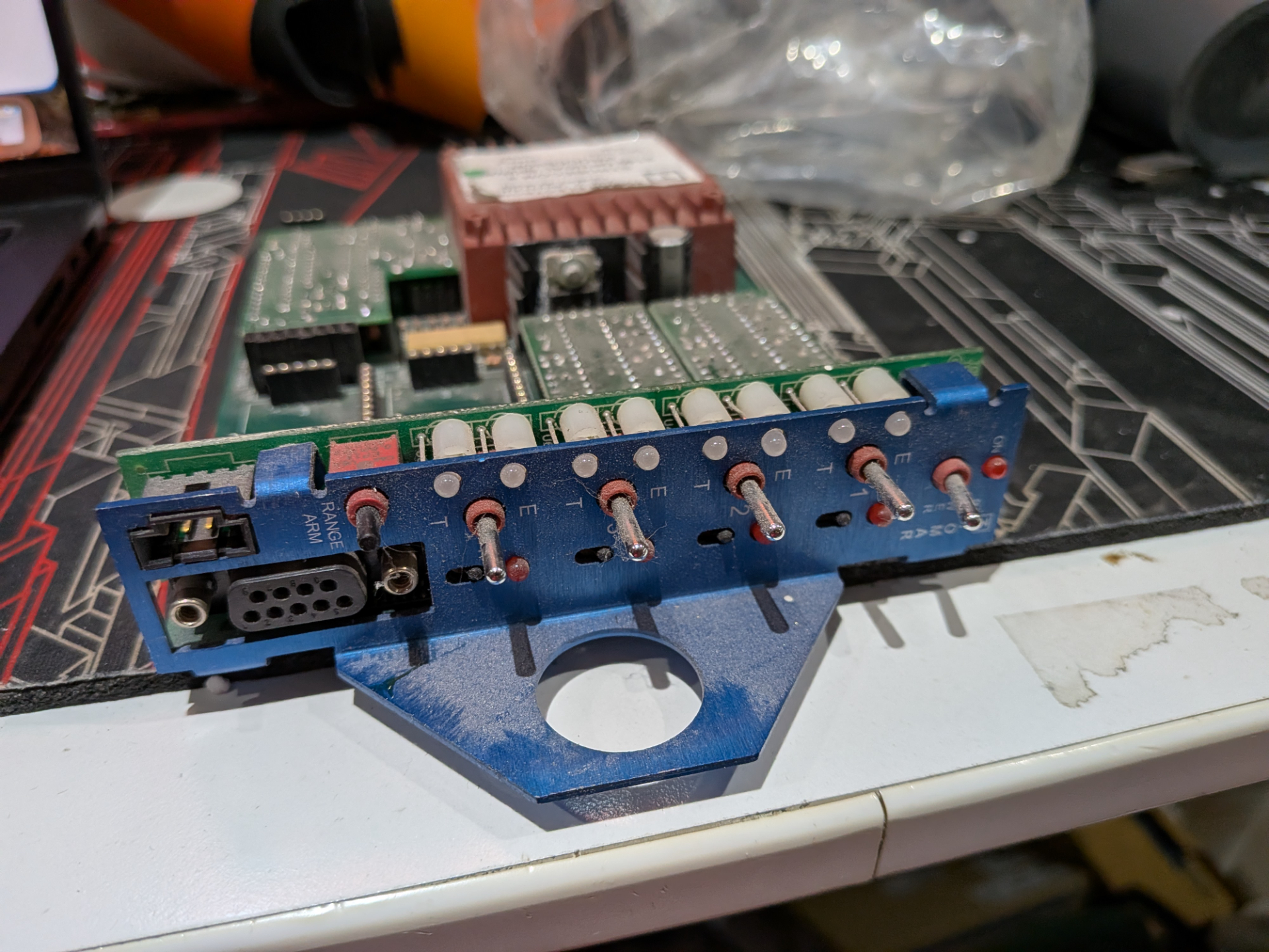
Just kidding. No ones taken away my eBay account yet so I bought my own Tomar Strobecom 2140 Optical Signal Processor (OSP). The same one listed in the VicRoads specification. This was a bit of a risky purchase because at this stage I didn’t know how much smarts were in the detectors vs the optical signal processor. It’s possible that the detectors decode the ID and just pass it to the signal processor… Ideally I would have purchased detectors as well, but those were on the much more expensive side.
At this stage I have a OSP, with no rack to put it in, no detectors, and no emitters. Usually this is fed from 240v off the traffic controller card slot. I don’t want to deal with mains, so figured out where 5v was being regulated and found some pin headers to supply my own power. The card itself has a PIC for each decoding channel, and then a central controller. They talk over I2C - my card had two channels installed. There’s a RS232 port used for configuring/talking to the central controller. The switches on the front allow testing that the card is functioning correctly - important to note here that these switches do not create test signals on the decoders - it just tells the decoder to send a preempt signal to the main controller.
So simple, we turn it on, use the software to configure the controller to allow everything, then throw some signals at it to see what decodes.
Even traffic light yaks need shaving
It was pretty easy to identify the baud rate (4800 8N1) of the RS232 connection, however the software to talk to the card isn’t available online. You can purchase it from Tomar for $600.00 USD - which is pretty rough that you have to buy along side the hardware - yay capitalism. Even if I did sink money on that, I wasn’t sure if they would actually sell it to me.
Configuring the card was important as I needed to know what codes were configured and have a way for automating logging of successful detection.
This stumped me for the longest time as I couldn’t figure anything out of the output by just guessing its protocol.
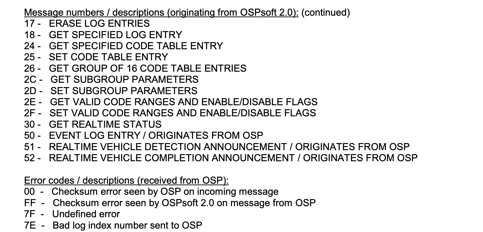
That is until I found a really old copy of “OSPsoft 2 User Manual” using the way back machine on the Tomar website.
This little section of the manual provided the hex values of the commands and also what the error codes were - along with hints of the data format.
From that I was able to piece together enough information to change ranges, enable uncoded signals and look at logs. The other part was that the user interface in the manual nearly matched the data that was sent in each configuration message. So I was able to work through the screenshots to determine what bytes did what things.
There were a few fun quirks along the way. A lot of the values are hex encoded for some reason, and sometimes ascii encoded. For example getting or setting a sub group requires sending a byte with the ascii encoded number of that group so for group 1 would would send b'1' using Python. However there are 16 sub groups and you can only send a single byte for this parameter. They actually overflow the ASCII conversion so the 10-15 become b':', b';', b'<', b'=', b'>' and b'?'.
With the uncoded ID enabled, I was able to wire up an Arduino Nano and generate a 14.035hz tone and successfully get the unit to show an emergency preemption light on the front panel - along with log some output. Seeing that little light come on was a relief because up until this point I wasn’t sure if the signal processor actually processed the pulses.
Coded messages
The next challenge was coded messages. The first thing I did was run a bunch of tests with the unencoded message to understand what the limits were. It took 33 bits to trigger an unencoded preemption, the min pulse gap length was about 71.010ms, and the longest was around 71.260ms.
From the GTT patents I expected there to be two pulse lengths, a short and long, and based on the spec sheet from Tomar it supports 65000 vehicles - so roughly 16 bits of vehicle ID information.
We still have some questions though:
Is there a preamble - and if so how long and what does it look like. If not, how does the system know the start of an ID
Is there a checksum
Are the vehicle IDs using some sort of gray code or De Bruijn sequence?
I pretty much started with shoving random bit patterns into the system and logging what came out. The intention here so to find something that decodes - even if we don’t know what it means. We vary the pulse delays from the range we found above.
This didn’t get me very far, so I built something a bit more controlled. I programmed a bunch of formats/rules to try - such as repeat the sequence every 15,16,17,18 bits. Use a nominal frequency every 2nd pulse.
My thought process is that if a checksum existed, it would be a max of 16 bits. Eventually we might find a match. I tried a bunch of experiments.
Eventually one of the experiments returned two different successful decodes. The pulse stream was logged. The problem was that playing those back again didn’t result in a decode. I did however find that playing it back it would decode once in maybe 10-20 decodes. Not great but it’s a starting point. The pulse stream was effectively repeated at 17 pulses, the last pulse delay was long.
From here my thought was that one of the bits were being flipped creating a valid preamble. I started flipping bits but this made decoding worse! If there’s no preamble - how does it know the start or finish of the vehicle ID?
The secret third option. The last pulse in the repeating pattern was a long delay. What if I bump just that pulse out by even longer. Success, reliable decodes.
I ran through some ranges of pulse delay timings and figured out reliable timings (note that were are using delay/delayMicroseconds in Arduino, so aren’t exact figures. I don’t have a great way of measuring exact pulse delay times)
l 71215  +/- 10 (safe)
s 71090  +/- 10 (safe)
p 71260 +/- 10 (safe)
[p,   s,s,s,l, s,s,s,s, l,l,s,l, l,s,s,s] (repeat at least twice)
Decodes as 61,223 (0xEF27)
The vehicle ID isn’t encoded in any special way, the key part is having an extra slightly longer delay for the first/last pulse and repeat at least twice (to get up to 33 pulses - both sequences must match).
Transmitting
As a PoC I built my own little detector. It’s not using the amplifier circuit, is missing all the filtering and is generally just terrible because I don’t know what I’m doing - but it works well enough to test.
In the video I demonstrate IR signal triggering the signal processor for a coded Strobecom II signal.
I also built using a Raspberry Pi Pico (important, the PCB must be pink) and connected an IR LED to it via a resistor.
#define l 71225 - 0xffff
#define s 71100 - 0xffff
#define p 71270 - 0xffff
#define LENGTH 17
#define on 200
unsignedint payload[LENGTH] = {p, s,s,s,l, s,s,s,s, l,l,s,l, l,s,s,s };
int pos=0;
voidsetup() {
pinMode(0, OUTPUT);
digitalWrite(0, LOW);
}
voidloop() {
delayMicroseconds(0xffff-on);
delayMicroseconds(payload[pos]);
digitalWrite(0, HIGH);
delayMicroseconds(on);
digitalWrite(0, LOW);
pos++;
if (pos >= LENGTH){
pos =0;
}
}
I adjusted the timing a little bit for the Pico but now get reliable decodes with the above code by pointing the IR blaster at my make shift detector.
But I still need to find the vehicle ID to “hack” the system right?
Yes. Kind of. Maybe
Some of the Tomar controllers don’t actually permit configuration. So as long as you configure an ID within the default range you are done.
Systems that do allow configuring - might be left with the default configuration. As above, if this is the case, you are done.
For systems that are configured, we should look at how that works. First quirk is that the controllers I’ve looked at require setting a ID range. This is a max of 1000 sequential vehicle IDs. This is due to the limited amount of memory on the controllers. So while it can decode 65,000 vehicle IDs you must set a range, such as 4000 to 5000, that your system will use. Inside that range you can enable/disable different IDs. By default they will all be enabled. I suspect in most cases this is most the configuration done.
In the case that the controllers have disabled all vehicle IDs by default, then you can expect maybe 50-100 vehicle IDs to be enabled in a typical system. Given that it takes 2.5 seconds to send a signal, binary searching this space isn’t all that time consuming when its 100/65000 codes.
The worst case is that the system is programmed with a single ID. That would take 45 hours. On the flip side, if the system is coded with a single ID, it’s really hard for them to change that ID as multiple vehicles will need to be reprogrammed.
What can be done?
Both Tomar and GTT know that these systems are insecure. Both have various patents (sigh) of alternative authentication schemes, such as using a combination of IR and radio. I imagine most traffic agencies are moving away from this optical based approach anyway. Every state/area has different approaches to EVP.
So can the Flipper Zero be used to change the traffic lights?
Probably. The thing is though, I don’t own one and I don’t have a Strobecom detector.
The timing on the Tomar system is tight, flashing roughly 14hz isn’t good enough. If your LEDs don’t have a quick rise time, then they’ll get filtered out and if the system requires codes you need an active code. There’s also nothing stopping you from adding a xenon flasher (apart from the risk of high voltage electronics) to a Flipper Zero.
I’m pretty certain that it’s possible to get a Flipper Zero to trigger Strobecom II preemption - I just don’t think anyone has done it yet. Opticom on the other hand, probably has happened.
Further research
My OSP only lets me configure up to the advertised 65,000 IDs. That means there are 536 IDs that are unconfigurable. After this post goes up I’m going to try to send some of these IDs to see if they trigger anything fun.
I’ve placed my notes, Pi Pico code and OSP reverse engineering in this GitHub repo.
For those not familiar, Horus Binary is a high altitude balloon telemetry system. It’s goals is to overcome some of the challenges compared to other general purpose systems as high altitude balloons have unique challenges.
Challenges with high altitude balloon telemetry
Telemetry is important to track the location of the balloon to aid in recovery, but also to downlink data in case recovery isn’t possible. Often several payloads are flown and some flights contain multiple communication methods, not just Horus Binary. As with the majority of things mentioned in this post, the RF downlink is a series of compromises specifically chosen to solve a problem. For example you can run an entire DVB-S transmitter and have a live feed of the video footage - but for this you need yagis and a fixed location - limiting the possibility of recovery without another solution.
It’s pretty common for a high altitude balloon to reach 30km altitude. So even if you are standing directly under the balloon at that time, it’s some distance for wireless communication. While the distance is pretty great, the advantage of being a balloon is there’s rarely any obstruction between the receiver and transmitter - so we win back a little bit of SNR from having the line of sight advantage. To handle the distance we want something with a low baud rate and error correction. While typically we have line of sight, we still want to receive telemetry at launch and landing, where conditions might not be perfect for RF.
Balloons can only lift so much. Large balloons require more helium, more expensive, harder to launch and may require more regulation/rules. So the payload also needs to be light. Launching a IC-7100 radio isn’t a great option. But down sizing also imposes some more challenges. Smaller payload means less battery, less transmit power. Horus Binary is often transmitted from repurposed radiosondes, powered by one or two AA batteries with an RF output power in the tens of mW. The lighter transmitter solution allows for more weight dedicated to science.
Now one of our key requirements is trying to recover payloads. This means we want to receive a telemetry packet on, or as close to, where the payload hits the ground. We could build a system that let you send kilobytes of data - but at the low baud rate, it would take forever to send. These balloons are falling at rates around 20km/hr, so if we receive a packet every minute then very likely we might not receive a low enough altitude packet to accurately determine the landing location and recover the payload. So we want to keep the payload size short.
So what about existing infrastructure, like satellite, cellular , LoRa networks. These actually do get used on flights, but they have their shortcomings. For cellular there might not be coverage at the landing location, and since cell towers generally point their antennas down or to the horizon the coverage can be patchy in the sky. For satellite there’s weight constraints for high speed links, and for most small trackers the update rates can be minutes or more. LoRa is a similar story with low update rate (if being a good citizen) and you need to rely on good area coverage. So if we aren’t using existing infrastructure, then we need to bring our own. That means having recovery vehicles able to easily receive it, and a network of stationary receivers where possible.
For a mobile receiver this means we don’t want a fancy multi element yagi tracking system. We want a simple dipole or cross dipole that can used on a moving vehicle. Likewise on the payload, we want an antenna with little gain in any one direction, as we won’t be sure which way the antenna is facing.
Summary of requirements
Low SNR requirement
High update rate
Reliable data
Low power usage
Mobile receiver
This results in some of our design constraints for a protocol:
Low bit rate (100 baud)
Small packet sizes (< 128bytes)
Low power transmitter
Horus Binary v1/v2
Horus Binary v1/2 have been around for awhile now and pretty well established in the amateur high altitude ballooning space. It uses a well tested 4FSK 100 baud modem with Golay for error correction. The payload itself is 20 (v1) or 30 (v2) bytes, with an additional 2 bytes for a checksum.
Anyone can receive the telemetry by using either a sideband radio receiver or software defined radios like the RTL-SDR, which keeps hardware costs down.
We don’t need to dive too deep into RF for this post as this modem is well established and pretty good quality, but we do need some quick fundamentals. Horus Binary uses 4 times frequency shift keying (4FSK) - or put another way, 4 tones to indicate ones and zeros.
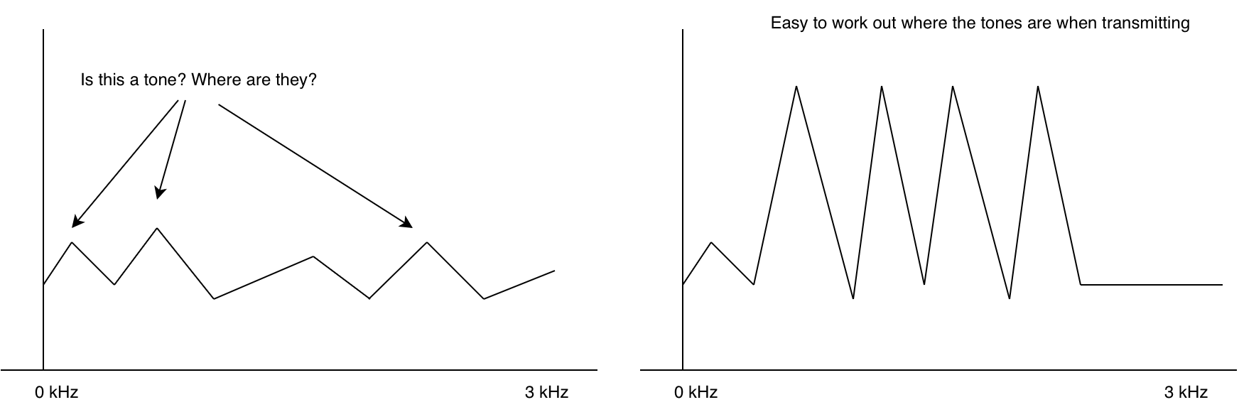
If you tune a radio to a frequency where there’s no station, you hear noise. This is also true for data modems. Without any sort of checking we’d get a random string of ones and zeros. (sometimes this is used to generate random numbers!). In fact without anything transmitting the modem doesn’t even know where the signal/tones are.
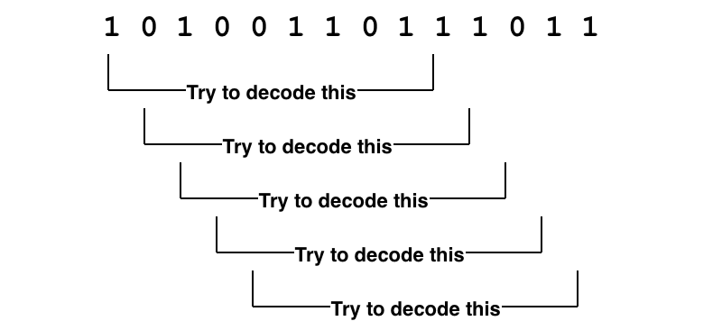
This is why at the start of an RF packet, often we transmit what’s called a preamble. A sequence that is super easy for the modem to figure out where the tones are. With the modem synchronized, the next problem is decoding. The modem itself doesn’t really know whats valid ones and zeros and whats invalid.
If we take the ones and zeros and try to decode each one and check its checksum, then we would waste a lot of CPU and possibly not even keep up with the incoming data. We really need a way of quickly seeing if a packet is actually likely to be a packet.
For this we use a “unique word”1. A series of bits that are always at the start of a packet. We can accept a few of these bits to be wrong due to noise by setting a threshold of valid bits. Effectively don’t try to decode the packet unless the unique word is at the start.
Putting this all together for Horus Binary v1/2 we have
30 bytes is not a lot. So what is in there, and how do encode/decode it? For v1/v2 a simple struct packing is used. The table below shows how the fields are stored. By packing the data down as binary data without any tagging or delimiters a lot of useful information can fit inside a small packet.
Byte No.
Data Type
Size (bytes)
Description
0
uint16
2
Payload ID (0-65535)
2
uint16
2
Sequence Number
4
uint8
1
Time-of-day (Hours)
5
uint8
1
Time-of-day (Minutes)
6
uint8
1
Time-of-day (Seconds)
7
float
4
Latitude
11
float
4
Longitude
15
uint16
2
Altitude (m)
17
uint8
1
Speed (kph)
18
uint8
1
Satellites
19
int8
1
Temperature (deg C)
20
uint8
1
Battery Voltage
21
???
9
Custom data
The astute among you would have noticed the “Custom data” field. If there are no delimiters or field separators in the format, how does one decode that data into fields again. Like wise the Payload ID seems to be a number, rather than a callsign - but on sites like SondeHub a callsign is displayed.
Horus Binary v1/2 rely on two files that are regularly updated to resolve the payload ids to callsigns and the rules to unpack the custom data. This means that receiving stations need to have internet access prior to the flight to get the latest data and launch operators need to submit pull requests to get their callsign and custom data allocated.
The smallest a custom field could be was a byte.
Handling different sized payloads
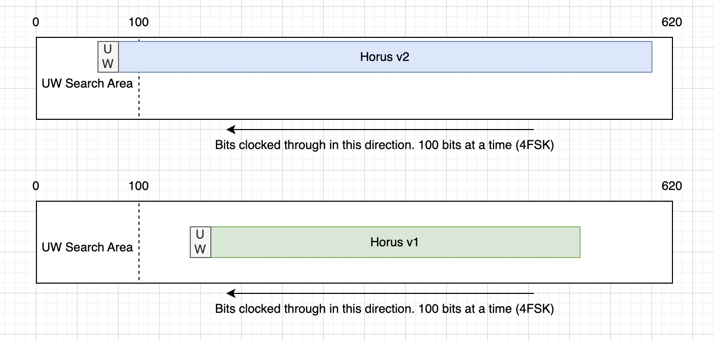
Horus Binary v1 and v2 use different payload lengths, however receivers don’t need to configure which version they are receiving. How does that work? We try both
In v1/v2, we have a buffer that is just longer than the longest packet. As data comes in we shift the bits to across so that new data is always on the end of the buffer. Then we search the start of the buffer for the unique word. If we see the unique word, we try decoding both Horus Binary v1 and v2 - Only one of the checksums should pass, if it does, then we have a valid packet.
This however means that we have to wait the same period of time for v1 packets as we would for the much longer v2 packets.
v1/v2 shortcomings
Now lets summarize some of the shortcomings for v1/v2
Launch operators require a central authority to bless their callsign ID and custom payload data
Receiving stations need to regularly phone home to get latest configs
Custom payload data is rigid and inflexible
There is latency in decoding smaller packet sizes
Small size of 30 bytes can limit usefulness for some missions
Additionally the software for decoding Horus Binary had some issues:
Pypi packages didn’t have wheels, resulting in users having to build their own versions
The modem itself is a C executable which had to be built separately
Horus GUI Windows app required reusing a handcrafted DLL, limiting ability to update the modem component
Limited testing / no testing framework meant a lot of manual testing before releases and changes
While still meeting the constraints listed above, can we do better?
Horus Binary v3 and ASN.1
This is where Horus Binary v3 comes in. Horus Binary v3 is an attempt to address the above issues and has taken months of planning, discussions, development and testing. Most of which has been figuring out which things to compromise on. While apps today are running entire browsers and gigabytes of memory, the development of Horus Binary v3 meant squabbling over single bits, let along bytes.
One thing I wanted was a well defined specification of the binary format. After investigating things such as protobuf, Cap’n Proto and many other encoding schemes I was somewhat surprised to find there’s limited options for unaligned formats. Unaligned means that a field doesn’t need to be whole bytes. A field can start and stop at any bit offset, rather than a multiple of 8. Shifting from a byte aligned to unaligned format was important to the design goals as it let use save bits from fields that would otherwise need as much range in their values. Eventually settled on ASN.1 using it’s Unaligned Packed Encoding Rules (UPER).
For example I can describe a temperature field like so:
internalTemp INTEGER (-1023..1023) OPTIONAL
In this example the internalTemp field can have a value from -1023 to 1023, and it is optional.
ASN.1 defines a bunch of encoding rules. We can take the above specification and encode it into XML, JSON, or bits. What’s great about UPER is that it takes into account the size constraints like (-1023..1023), so that the final encoding for that field is just 11 bits long for the data itself. The optional flag is an additional field to mark if the field is actually present. So if internalTemp isn’t sent in the payload, then only a single bit is consumed.
Encoding a value of 123 for internalTemp results in 12 bits:
Optional flag   Number
1               100 0111 1010
From experience we know that several fields are always sent - such as Payload ID, sequence number, time of day, location. But we also know that each payload is different and will may have none, one or multiple of sensors like temperature, voltage, pressure, counters. We can place these fields into our specification and operators can pick and choose what they need.
CustomFieldValues ::= CHOICE {
  horusStr   IA5String (FROM("abcdefghijklmnopqrstuvwxyzABCDEFGHIJKLMNOPQRSTUVWXYZ0123456789_ +/=-.")^SIZE (0..255)),
  horusInt   SEQUENCE(SIZE(1..4)) OF INTEGER,
  horusReal  SEQUENCE(SIZE(1..4)) OF REAL,
  horusBool  BitFlags
}

AdditionalSensorType ::= SEQUENCE {
  name    IA5String (FROM("abcdefghijklmnopqrstuvwxyz0123456789-")^SIZE (1..20)) OPTIONAL,
  values  CustomFieldValues OPTIONAL
}
AdditionalSensors ::= SEQUENCE(SIZE(1..4)) OF AdditionalSensorType
Additional to the built in sensor types, we also have an AdditionalSensors field which uses ASN.1’s CHOICE function to allow an operator to pick what kind of data type they require. This could be a REAL, INTEGER, BOOLEAN or a STRING. This allows some amount of self describing without the need of central authority.
Since fields and sensors can be optionally added and removed a payload doesn’t need to send all it’s sensor data down, all the time. While location is important for recovery, sensors can be sent sequentially to fit in packet sizes.
Payload IDs have also been replaced with strings. While this consumes more bytes it allows freedom to develop and launch without having to request a payload ID number. ASN.1 UPER rules allow us to define what characters are allowed, and by doing so this reduces the per character cost to just 6 bits per letter.
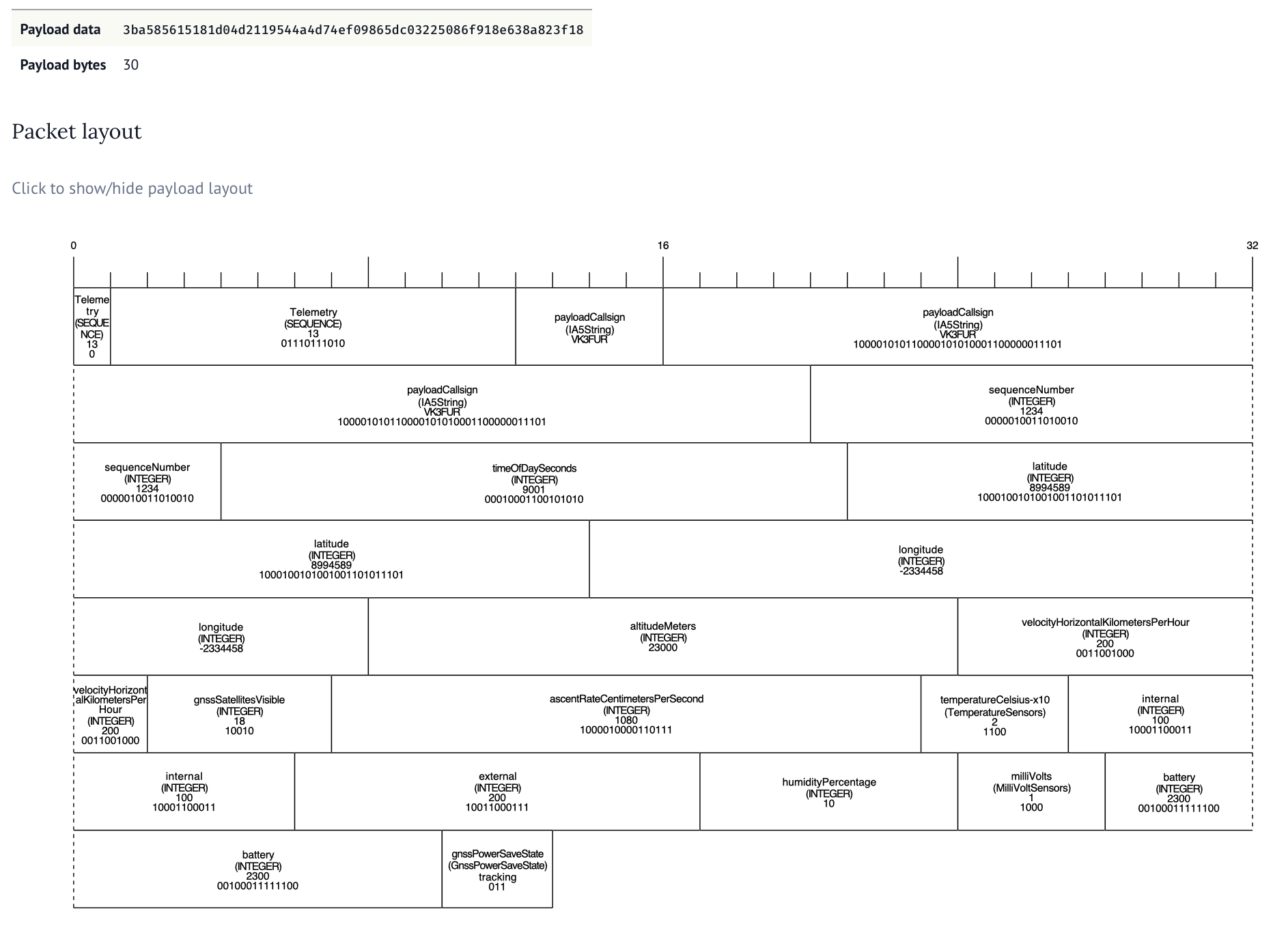
To help develop the format and understand the packet length costs we built a tool to visual the ASN.1 encoding. Along with a series of unit tests to make sure the encoding was working ok.
The tool allows for changing the ASN.1 specification and input data, allowing payload developers to make decisions on what data to send when and can be found here. It took a lot of collaboration and thought to figure out good compromises. Adding an optional field always consumes one bit so we want to work out which fields are always sent and which ones might not get sent. If we made every field optional we would waste nearly an entire byte in optional flags.
For each field we want to also constrain the size of that field - this means figuring about the absolute min and max values for each type along with the required resolution. I wish ASN.1 had support for fixed precision.
But 30 bytes still doesn’t get us much data. What if we have a bunch of extra sensors.
Longer packets and checksums
We’ve expanded out the packet size to allow 32, 48, 64, 96 and 128 byte long packets. While we don’t recommend sending 128 byte packets as the transmission time is longgggg, it’s an option for those who need it. The 48 byte packet seems like a really nice middle ground balancing the packet size with additional telemetry.
But this long packet poses a problem with the current solution. The latency would increase significantly if we have to wait for the longest packet size before checking all the combinations.
This is why we’ve flipped around the way the packet is attempted to be decoded. As soon as a particular format has enough bytes to decode, we try to decode it, regardless of where it is in the buffer. By switching to scanning for the unique word as the bits come in we are able to decode all packet sizes with the smallest amount of latency.
There’s still one problem though. If we have a 32 byte packet that could be v2 or v3, how do we work out which decoder to use? Our final change of the telemetry format was to move the checksum to the start of the packet. So we check the checksum at both the start and end of the packet. If the one at the start passes, it’s v3 and if the one at the end passes it’s v2.
Transmitting
It’s all well and good being able to generate these complicated unaligned structures in Python on a machine with gigabbytes of RAM but we need it to run on a repurposed microcontroller. For this we use the ASN1SCC compiler.
This can take an ASN.1 specification and turn it into light weight C code.
// some setup and error code removed for brevity
horusTelemetry testMessage = {
.payloadCallsign ="VK3FUR",
.sequenceNumber =2,
.timeOfDaySeconds =30,
.latitude =90,
.longitude =90,
.altitudeMeters =1000,
};
horusTelemetry_Encode(&testMessage,&encodedMessage,&errCode,true);
The ASN1SCC is pretty light weight compared to other tools like asn1c and asn1tools. We saw an increase of roughly 6 kilobytes to the compiled output.
Two problems with ASN1SCC is that it’s opinonated about space vehicles. This means that extension markers are currently out of scope and not supported but we were able to work around that placing a dummy optional field. The other is that ASN1SCC assumes you might build a packet that is as long as the longest possible - causing excessive memory usage. We worked around this by building our own assert handler and allowing smaller buffer sizes.
Packaging and tests
There’s three main way Horus Binary v3 is received. Using horusdemodlib’s horus_demod command in a shell script, webhorus in the browser and the horus-gui desktop application.
Horus-gui uses horusdmeodlib which demodulates the signal using libhorus C library. The result is that for both horus_demod shell script method and horus-gui options, C code needs to be compiled using cmake. This means extra compiler tools to install and extra steps for the user to follow.
An additional concern that by using ctypes to access the library in Python there is risk in programming errors causing subtle memory corruption bugs that are hard to catch. We have to carefully define all the arg and return types for each function call like so.
To resolve these issues we made the change from ctypes to cffi. This makes Python in charge of the compiling, and automates the creation of a library which handles the args and return types correctly. Additionally we converted the C based horus_demod command to Python.
With Python now in charge of compiling we could start using cibuildwheel to automate making Python Wheels (these are precompiled ready to go packages that are built for each desired Python version and architecture). This means the majority of our users do not need to compile to install and use horusdemodlib and simplifies the build process for horus-gui.
A user can now do pipx install horusdemodlib to install decoding and uploading utilities2. No compiling needed in most cases.
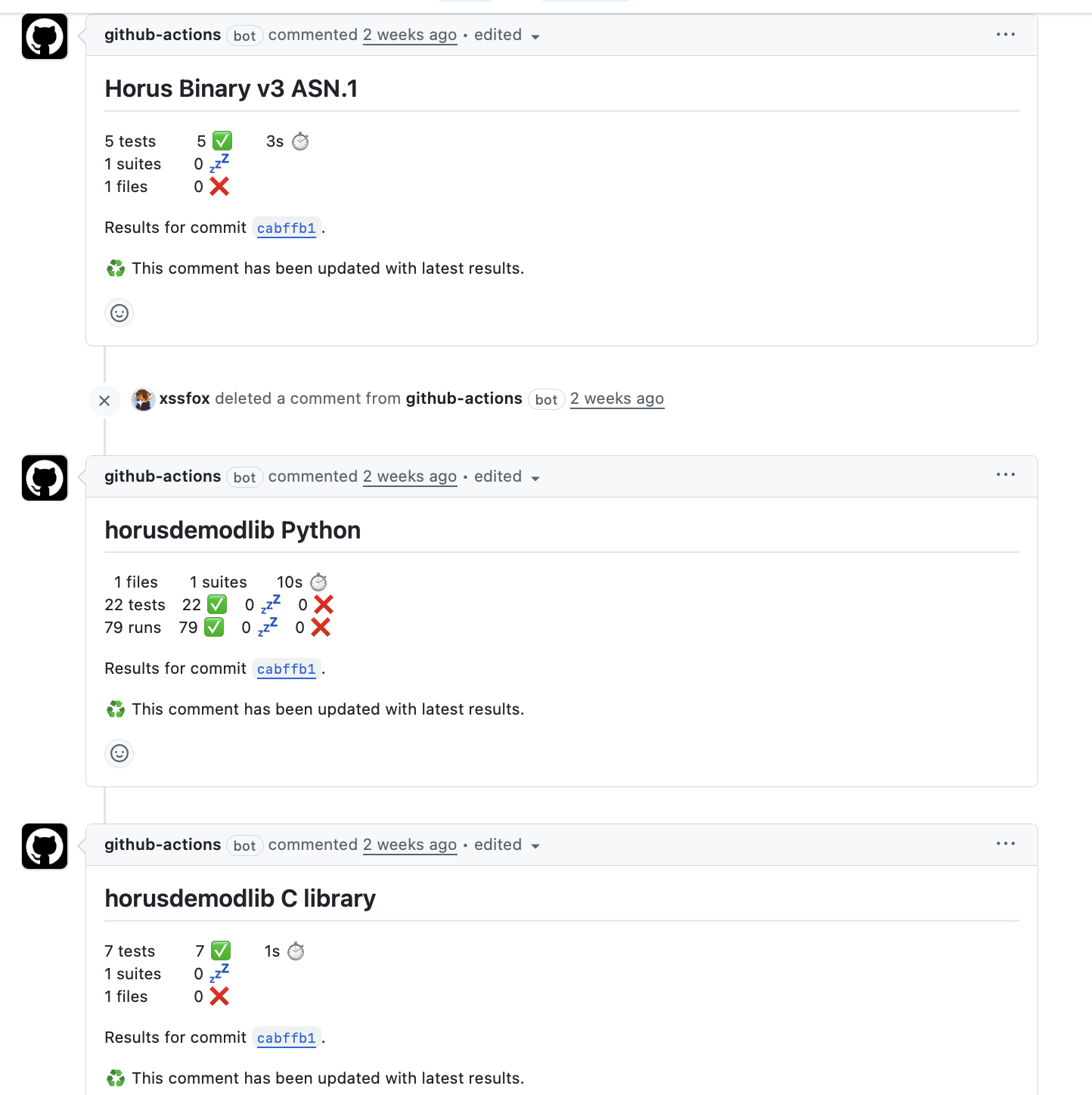
While there were a few manual test scripts, these weren’t run as part of any automated workflow, nor did they use any testing framework. These were updated, added to and enhanced to run using Python’s unittest and report as part of GitHub actions workflows.
While not exhaustive, it gives us a lot more confidence prior to release.
Fin.
And that’s it. horusdemodlib and related apps were released yesterday. There’s been numerous test flights leading up to the release (many thanks to everyone testing, both from the transmitting side, and the receiving side). While there’s likely bugs and quirks, I’m fairly confident that V3 is good move forward for the project.
There’s still some things we want to work towards, such as easier receiving CLI app design, Debian packaging and possibly some micro python payloads. First up however, I’m taking a nap.
This post is going to be broken up into 3 parts. Why you shouldn’t listen to me. A brief history and current status of identity in Australia. Why the current state is a problem and some possible ways out of this mess.
Part 1. Don’t listen to me.
This topic is so far outside my typical domain that I’m going to be missing a bunch of issues, concerns and subtle quirks. This in an opinion piece and shouldn’t be taken as fact. I wasn’t even born in 1985 (this is important later) so I can only go by information passed down to me.
Where I do have experience is that I have had the joy of updating all my identity documents. I have been victim of identity theft. And I have had the joy of myID (formerly myGovID) not working. I also work in tech and often have consulted on design decisions regarding verification and identity platforms.
Part 2. WTF happened and why is this like this.
For non Australians (Australians can probably skip this paragraph) reading this blog we have a system of authenticating to government services called “myID” (I’m going to ignore just how horrible this name is). myID is an app that can be installed on a phone and is tied to an email address. A government website (and soon non gov) can use myID to authenticate a user. It has various levels of identity strength a user can have, Basic, Standard, and Strong. Basic is practically useless - it means you installed the app and filled in some forms. Standard you have validated some documents like a drivers licence, passport, medicare card. Strong is where your photo is validated. The thing about myID is that many government services don’t require it. You can often sign up an account without a myID.
Now when you setup a new phone with myID you have to validate all those documents again. Why? Surely I could just sign into the account again. Or maybe another question is - why is myID even different account then myGov.
My assumption here is that is we need to take a trip all the way back to 1985, before the concept of a digital ID was even considered. The “Australia Card” idea was floated. The idea of the Australia card was to replace several government identity solutions and create a single solution that worked across both federal and state services. A big part of the Australia Card system was to crack down on fraud, tax evasion, terrorism and illegal immigrants. Effectively this was meant to be a magical cure for society. Every transaction would need an Australia Card number.
Now I should be clear here, I do NOT support the Australia Card proposal. The amount of tracking and overreach with that solution is immense, and I’m glad the proposal was eventually dropped. However it wasn’t without consequence.
The tax file system was extended, and every government service went along it’s merry way using their own identity systems, often having soft links to others.
At common law an adult may assume any surname by using such name and
becoming known by it. A surname is not a matter of law but a matter of repute …
The law of this country allows any person to assume and use any name, provided
its use is not calculated to deceive and to inflict pecuniary loss.
New South Wales Law Reform Commission, Names: Registration and Certification of Births and Deaths, Report No 61 (1988)
This leads to an interesting outcome in Australia. We don’t really have a concept of a “legal name”. It’s a bit more like “whatever the service your trying to use is willing to accept”, and since federal and state government services don’t have a central identity system, you instead have an identity at a service level. Your name might be different (either intentionally, book keeping error, or system design issue) on all of these:
State transport department (eg, vicroads)
State services (Service Vic, Service NSW)
Medicare
MyGov
Tax office
ACMA
CASA
Local council
Births / Deaths / Marriages
Passport Office
Many many many more
And this is before we even get to private companies trying to validate ID.
Part 3. Why is this a problem
A large part of the Australia Card (valid) opposition is that data tracking is an invasion of privacy. Additionally the threat of cutting off services to those refusing to use it or don’t have access to it hostile. It risks cutting off communities from services they need to live.
At the end of the day though, even without the Australia Card, the government still kind of “won” and fucked everything up. Sure, not every transaction was tracked, but we have tax file numbers and business transactions are heavily tracked. Banks are required to report suspicious transactions, as low as $10,000. Every service we interact with today asks for a birth certificate number, or drivers licence. Our laws require companies to store KYC (know your customer) data for long periods of time. The government will happily destroy the lives of hundreds of thousands of lives through shitty data matching - regardless of any sort of Australia Card.
When my identity was stolen in 2018 and used for phone toll fraud I was informed to update my drivers licence number (side note here, if you don’t have a drivers licence - identity becomes hard mode in Australia. Fuck cars.). This is good advice - however - the transport departments create drivers licences to identify who has a drivers licence. Yes a bit of a tautology, but the key point here is that the transport department is not designing drivers licences to be a generic identity document. Their use case is for police to check if you are allowed to drive. This has likely changed since my identity theft incident due to more recent data breaches, but at the time QLD did not allow changing the drivers licence number (CRN) unless a police report recommended it - and police in Australia do not investigate or write reports about fraud that has happened from overseas (amazing I know). I was unable to change my CRN. From the point of view of Transport and main roads QLD, my drivers licence could still be used for the purpose it was designed for. They would happily reissue me a new drivers licence with the same number…
So this is why myID asks for a bunch of documents to validate your identity. It’s trying to be the Australia Card scheme, without being the Australia Card scheme. A trojan horse of central identity. But it falls short because of our mess.
Often fails to link identities because the data is slightly wrong or different between services
Name changes can only be verified in NT, SA, TAS and ACT. lol.
Even name changes in those states don’t work work if you don’t have a name change certificate (often the case for people who have updated their birth certificate during gender transition)
You used different names between services
We’ve created a link between all the accounts, thus defeating the point of opposing Australia Card
Fraudulent users can just choose not to use myID in many cases and falling back to uploading legit looking documents
myID branding and usage in gov services is confusing at best. There’s no way for a user to learn what is safe and normal
DID YOU KNOW THAT MYID ISN’T EVEN THE ONLY POSSIBLE PROVIDER??!?. That’s right, we might see more. Because free market and such, Australians need to know that they aren’t just looking for “myID” but also “Australia’s Digital ID System” tick. Make sure that your signing an “Australia’s Digital ID System” by checking this completely unhackable image. I swear to god.
So today what happens when a user is trying to access government services is a mishmash of identity verification methods, sometimes myID, sometimes optional, sometimes custom built. Users are trained to just send pictures and numbers of their identity documents to sites and services without much thought. Every state has implemented it’s own poorly implemented digital drivers licence.
Hotels will photocopy, scan, and in some cases save into a public file share your drivers licence when you check in. The same identity document that can be used to access all other gov and private services. When identities get compromised we can’t even trace back to where they were stolen from.
With the government imposed social media ban for under 16s more and more Australians are having to validate their age online - often using the same identity documents that allow all access to their life. Each week we receive a “privacy and security of our users is a top priority.” email and wonder what our identities will be used for this time.
The state today is:
The government still doesn’t care about our privacy and tracks us anyway
All our identities are linked if we like it or not
For many people, proving our identities is hard or painful
The digital ID solutions today don’t provide a secure way of verifying our identity or anonymously (both parties) proving our age to third parties
Companies are expected to keep copies of our identity documents
The political nightmare that was the Australia Card has naturally tainted any possible fix to this problem, but I think we can fix this.
(the big ask) Government repairs it’s social contract, stops treating it’s citizens like criminals and actually provide services to citizens. Provide consent models and allow people to opt out of things. A digital ID should be optional. Using one should be privacy preserving and require consent.
myID needs to be the one and only way of proving identity online, both for gov and private sector
Private sector should be legally required to provide myID verification option. (there’s some caveats and concerns around this. The intention here is to provide a known secure way for people to verify identity while ensuring the private sector doesn’t store documents)
Drop drivers licences as a form of identity and allow myID to be a real identity, not just a meta identity.
I think it’s possible to build digital ID systems that help users be more secure and more private online, but it also relies of the government not fucking it up - which I know if a big ask.
Part 100 point check
The 100 point check “system” is the dumbest concept. Lets compare some 100 point checks across services
Renting - seemingly different per agent
Passport: 30
Drivers licence: 40
Birth Cert: 10 ????
Bank statement: 20
Why is this like tennis scoring. You could normalise all these values down. No point system has an identity document that is worth “1” point. Further to this, nearly all the 100 point systems require $x category A documents and $y category B documents. The numbers don’t even matter at that point!